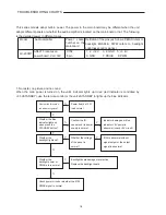
This series models adopt built-in power. The power to the main board may be different when the unit
adopts different panels or whether the audio amplifier is located on the main board or not. The following
is the detailed power in different cases.
Model Audio
amplifier
Power socket
number on the
mainboard
Definition of the pins (as follows, PBIAS refers to
backlight ENABLE, PWM refers to backlight
brightness control signal.)
LC-20XR1
AN5277, locates on
power board, Vcc=18V
X702
8 pin
1, 2: +12V 3, 4: GND 5: +3.4V
6: GND; 7: PBIAS 8: PWM
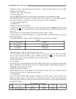
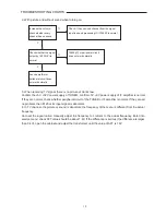
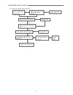
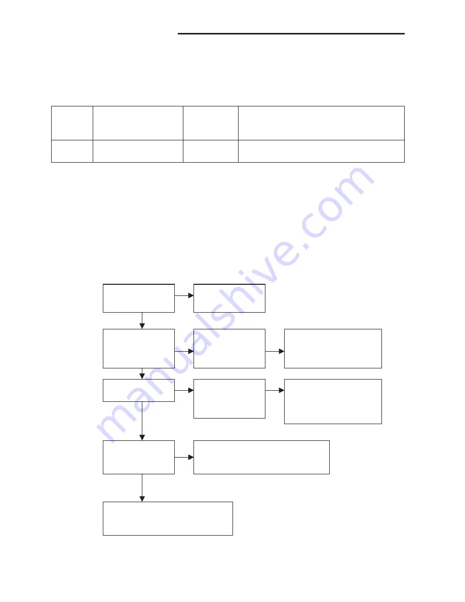
1. No raster, no picture and no sound
When the main power is turned on, the unit’s indicator lights up in red (red indicator is controlled by
+3.3VSTANDBY), use the remote control or the unit’s STANDBY to lights up the blue indicator.
Whether the IR board’s
red indicator lights up?
Power board’s +3.3V
is abnormal
Whether the blue
indicator lights up
when press the
STANDBY button?
Confirm the IR
sensor and its powe r
supply is normal
Indicator damages or blue
ind9V power is
abnormal (check +9V circuit)
Whether the
backlight lights up?
Whether the voltage
of the panel is
normal?
8125is abnormal without
signal output or the output
signal is abnormal
Whether the backlight
power or PBIAS pin is
l
Backlight boarddamage or protection.
Replace the backlight board
Whether the
backlight power or
PBIAS pin is normal
Check power circuit or whether the 8125
PBIAS signal is normal
N
Y
Y
Y
Y
Y
N
Y
N
N
18
TROUBLESHOOTING CHARTS
LCD-20XR1AU.indd Sec1:18
LCD-20XR1AU.indd Sec1:18
2006/07/13 11:59:28
2006/07/13 11:59:28
Содержание LCD-20XR1/AU
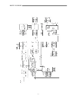
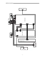
Страница 13: ...11 BLOCK DIAGRAM ...
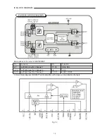
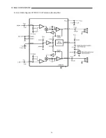
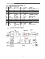
Страница 16: ...14 4 Inner block diagram of TPA1517 6W stereo audio amplifier 14 IC BLOCK DIAGRAM ...
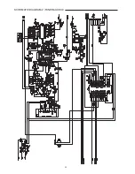
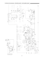
Страница 23: ...21 SCHEMATIC DIAGRAM 1 INTERFACE ...
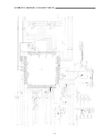
Страница 24: ...22 SCHEMATIC DIAGRAM 2 TUNER AUDIO ...
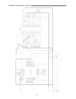
Страница 25: ...23 TO INFRARED BORAD SCHEMATIC DIAGRAM 3 SCALER FLI8125 ...
Страница 26: ...24 SCHEMATIC DIAGRAM 4 FLASH ...
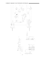
Страница 27: ...25 SCHEMATIC DIAGRAM 5 OUTPUT POWER KEY BOARD ...
Страница 28: ...26 SCHEMATIC DIAGRAM 6 POWER BOARD INFRARED BOARD ...
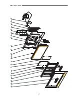
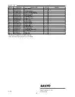
Страница 29: ...27 EXPLODED VIEW 1 2 3 4 5 6 7 8 9 10 11 12 13 14 15 16 17 18 19 20 21 22 23 ...

