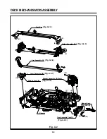


DECK MECHANISM ADJUSTMENT
4-13
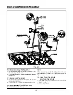
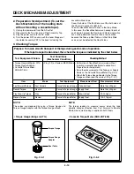
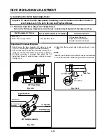
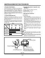
Purpose:To determine if the Mechanism is in the correct position, when a Tape is ejected.
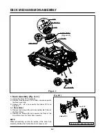
1. Mechanism Alignment Position Check
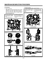
1) Turn the Power S/W on and eject the Cassette by press-
ing the Eject Button.
2) Remove the Top Cover and Plate Assembly Top, visual-
ly check if the Gear Cam Hole is aligned with the
Chassis Hole as below Fig. C-2.
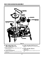
3) IF not, rotate the Shaft of the Loading Motor to either
clockwise or counterclockwise until the alignment is as
below Fig. C-2.
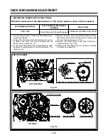
4) Remove the Screw which fixes the Deck Mechanism and
Main Frame and confirm if the Gear Cam is aligned with
the Gear Drive as below Fig. C-1(A).
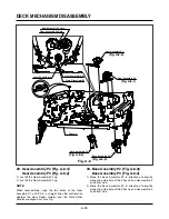
5) Confirm if the Mode S/W on the Main P.C.Board is
aligned as below Fig. C-1(B).
6) Remount the Deck Mechanism on the Main P.C.Board
and check each operation.
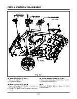
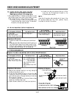
Gear Cam
Gear Drive
(A)
Mode S/W
(B)
L/D Motor Assembly
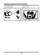
Gear Cam
Chassis Hole
Gear Cam Hole
(A)
(B)
(A')
(B')
Gear Drive Hole
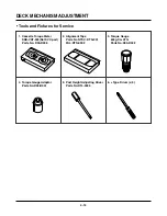
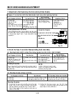
Test Equipment/ Fixture
• Blank tape
Test Conditions (Mechanism
Condition)
• Eject Mode (with Cassette ejected)
Check Point
• Mechanism and Mode Switch Position
Fig. C-1
Fig. C-2
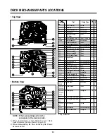
CHECK DIAGRAM
BOTTOM VIEW
TOP VIEW
Gear Cam (
o
) and Gear Drive (
o
) groove alignment
Содержание HV-DX2E
Страница 36: ...3 32 3 33 2 TU IF NICAM A2 CIRCUIT DIAGRAM EE MODE VIDEO TU MODE AUDIO COMBI SCART SANYO ...
Страница 41: ...3 42 3 43 7 TIMER CIRCUIT DIAGRAM SRC1203 SRC1203 LD601 C6G1 C6G2 100M 100M ...
Страница 45: ...3 50 3 51 PRINTED CIRCUIT DIAGRAMS 1 MAIN P C BOARD LOCATION GUIDE ...
Страница 64: ... 02 12 04 R17149A COMBI SCART SANYO DAP202K 3 76 3 77 6 JACK CIRCUIT DIAGRAM ...
Страница 69: ...LOCATION GUIDE 3 86 3 87 PRINTED CIRCUIT DIAGRAMS 1 MAIN P C BOARD TOP VIEW ...
Страница 70: ...LOCATION GUIDE 3 88 3 89 2 MAIN P C BOARD BOTTOM VIEW ...
Страница 180: ...SANYO Electric Co Ltd Osaka Japan Apr 03 ...