LV25300M
LV25300M
LV25300M
LC75030W
LC75030W
LC75030W
BPF
80
79
78
77
76
75
74
73
72
71
70
69
68
67
66
65
64
63
62
61
21
20
19
18
17
16
15
14
13
12
11
10
9
8
7
6
5
4
3
2
1
41
42
43
44
45
46
47
48
49
50
51
52
53
54
55
56
57
58
59
60
22
23
24
25
26
27
28
29
30
31
32
33
34
35
36
37
38
39
40
MIX
COIL
CF 10.7MHz
CF 10.7MHz
AM TRANS
CF 10.7MHz
AM-NC
NC STOP
TRIG
NOIZE
AGC
NOIZE
AMP
AM
2ndMIX
IF AGC
SD
S-METER
2ndIFAM
DETECTET
AM
1stAMP
Low cut
AMP
Limitter
AMP
S-METER
(DC/AC)
FM IF
FM
1stAMP
SD
2ndMIX
DETECTOR
MUTE
CIRCUIT
AUDIO
CIRCUIT
AFC
2.7V REG
450kHz
CF 450kHz
450kHz
OUTPUT
BUFFER
XTAL 10.25MHz
XTAL
OSC
3V REG
LOGIC
DIVIDER
NOIZE AMP
MAIN FIX
CIRCUIT
COUNTER
CURRENT
DRIVER
ANT selector
Diversity
charge
pump
R-CTR
BUS
IN 1
IN 2
IN 3-1
IN 3-2
IN 3-3
IN 3-4
BUS-
6/8bit AD
convertor
IF
COUNTER
ECT
1/4.1/6
1/8.1/10
NMOS Tr
swallow
counter
P-CTR
phase
det
PLL
POWER ON
RESET
DAC
CIRCUIT
AM
Lo/DX
M AGC
W
AGC
FM
Lo/DX
OSC
LPF
ANT-D
RF
RF
FE
Keyed
AGC
N
AGC
W
AGC
ANT-D
AM
1st
MIX
FM
1st
MIX
4.9V
REG
AMNCT
TEST1
TESTn
FL
(VOUT1L)
FR
(VOUT1R)
RL
(VOUT2L)
RR
(VOUT2R)
SUB Woofer
(VOUT3L)
Center
(VOUT3R)
BCLKO
LRCKO
FDATO
RSTB
PWDB
BUSY
DO
DI
CL
CE
IIS WS
IIS IN
IIS CLK
DIR AUX
DIR CD
DIR MD
PDO
VCO
XIN
XOUT
RDS_C
RDS_D
RDS_ID
SM-DC
SM-AC
MIC O
MIC P
MIC N
TEL O
TEL P
TEL N
CHG L (BTL)
CHG R (BTL)
CD L (OTL)
CD R (OTL)
MD L (OTL)
MD R (OTL)
AUX L (OTL)
AUX R (OTL)
REAR R
REAR L
NAV O
NAV P
NAV N
FM/AM
IF Signal
14bit
ADC
10bit
ADC
10bit
ADC
AM/FM Detector
FM Stereo
de-modulator
Digital
Data
Buffer
&
ADC
Control
24bit
ADC1
L
ADC2
R
R.S.E
Selector
RDS
Decoder
EVR
EVR
ADC Input Selector
Gain Control
PLL & VCO
FAVOR-30
CORE-1
Program Memory 1
Bus-Interface
FAVOR-30
CORE-2
Program Memory 2
Bus-Interface
DATA
Buffer
Data RAM
Data RAM
PERIPHERAL Control
Timing Control
Digital Interface
Receiver
IIS Digital Input
CCB Interface
SW
DAC
EVR
SW
DAC
EVR
SW
DAC
EVR
SW
DAC
EVR
DAC
EVR
DAC
DAC
DAC
EVR
Buffer
&
DAC
Control
Analog
Mixing
TEST
9
Car Audio
10
Car Audio
Features
Features
Block Diagram
Block Diagram
Functions
Functions
Features
Tuner/IF-DSP
■
FM F.E
■
FM IF
■
AM
■
PLL
■
Bass control
■
Switching control
■
Automatic adjustment
■
Connection to LC75030W (Interface)
■
Diversity function
■
Package: QFP80 (14 14)
■
IF signal input (450 kHz)
■
Processing for variable IF filter bandwidth
■
FM/AM demodulation processing, noise cancellation processing
■
FM stereo demodulation
■
RDS data demodulation circuit
■
Analog source selector and ADC
■
Electronic volume
■
DAC: 6 channels
■
Interrupt voice mixing
■
High-accuracy adjacent station detection algorithm and variable IF bandwidth filter
■
Waveform interpolation processing using two noise detection circuit and software systems
■
DSP software for optimum tuning, standardization, and adjustment-free operation
■
Analog output pin for dedicated rear sheet output that is independent of 6-channel DAC
■
Realization of low power consumption through optimized design of tuner circuit and DSP software
■
Package: SQFP144 (20 20)
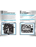
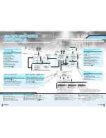
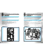
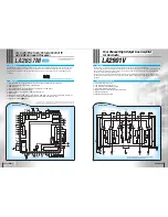
The LC75030W is a DSP for car tuner/audio.
1-chip Tuner
1-chip Tuner
1-chip Tuner
FM antenna sync circuit
FM-RF amp circuit
Differential
amp 1
Differential
amp 2
AM demodulation
FM antenna circuit
DAC block
AM block
FM RF amp circuit
FM RF sync circuit
Time constant
generator
Coil sync
circuit
Under
Under
development
development
Under
development
Under
Under
development
development
Under
development
CCB is a SANYO’s original bus format and all the
bus addresses are controlled by SANYO.
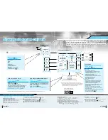
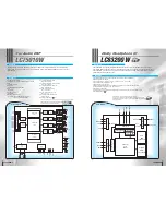
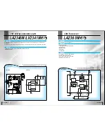
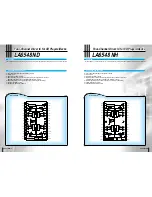
The LV25300M is a tuning system that supports the LC75030W (SANYO audio DSP) that allows the creation of standard
tuner modules. Various setting changes can be performed with the software of the control microcontroller according to the
intended application, making the LV25300M ideal for combined use with the LC75030W. Small tuner modules can be
developed with a smaller number of parts compared to conventional tuners and at a lower total cost. Since the LV25300M
has a serial bus (CCB SANYO bus), the number of communication lines with the microcontroller is reduced by 4 and line
routing problems during set production can be avoided, making a smaller board size possible. AM/FM wave demodulation
is done through digital processing by outputting the IF signal (450 kHz) of the LV25300M to the LC75030W.
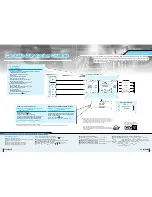
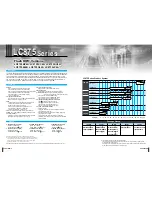
Since the LC75030W has a function to change the IF selectivity according to the level of adjacent interference, just two
10.7 MHz ceramic filters suffice to achieve both high sound quality and adjacent interference, which used to be difficult until
now because these are somewhat mutually exclusive characteristics. Moreover, the LV25300M comes with an antenna
switching diversity function that switches two antennas in response to various electric field changes during operation, a
malfunction prevention circuit that operates through antenna switching frequency detection, and a weak electric field
detection and antenna fixing circuit that uses S meter voltage, making stable reception possible.
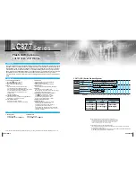
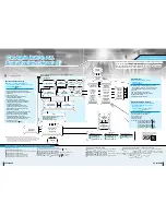
Optimum tuner reception is possible by outputting the voltages of the LV25300M' S meter output and the AM/FM IF outputs
to a DSP and judging the radio wave status in real time, and performance combinations and specification differentiation can
be performed by software.

