background image

 10 

4. ELECTRICAL ADJUSTMENT

4-1. Adjustment of Thermal Printer Head Resistance

Value

1.Install the ribbon cassette and paper tray, and turn the power

on without inserting a media card.

2.While pressing the LCD operation "+" button and "-" button

(to the right of the MENU button below the LCD) simulta-

neously for two seconds or more, press the Print button to

switch to the adjustment menu mode.

   The LCD panel displays "set-test."

3.Press the LCD operation "+" button six times, and select the

resistance value settings menu.

   The LCD panel displays "set-res."

4.Press the MENU button, and to switch to resistance value

setting mode.

   The LCD panel displays the resistance value (eg.: set-6210).

5.Set the resistance value on the LCD panel to the resistance

value displayed on the thermal head using the LCD opera-

tion "+" button and "-" button and the COPIES "+" button and

"-" button.

   The first digit is set using the COPIES "+" button, the second

digit using the COPIES "-" button, the third digit using the

LCD operation "+" button, and the fourth digit using the LCD

operation "-" button.

   The number displayed changes by 1 each time one of the

buttons is pressed, and after 9 comes 0.

6.End setting the resistance value by pressing the MENU but-

ton.

   The LCD panel displays "set-end."

7.Turn the power off.

4-2. Firmware Updating and Correction Data Updat-

ing

NOTE: Firmware updating and correction data updating can-

not be done at the same time.  Furthermore, if data is

stored on both sides of a firmware update media card,

updating cannot be performed.

1.Install the ribbon cassette and paper tray, and turn the power

on with the media card containing the firmware inserted.

2.Set to index mode using the MENU button, and while press-

ing the LCD operation "+" button and "-" button (to the right

of the MENU button below the LCD) simultaneously for two

seconds or more, press the Print button to switch to the ad-

justment menu mode.

   The LCD panel displays "set-test."

3.Press the LCD operation "+" button one time to switch to the

firmware update menu.

   The LCD panel displays "set-up."

4.Press the MENU button to start the firmware update.

   The LCD panel displays "f-up" or "h-up."

   While the firmware is updating, the ink LED lights.

   Do not remove the card while the firmware is updating.

   The LED will go off when the firmware update is complete,

and the unit will return to index mode.

5.Check to be sure that the ink LED has gone off and that the

unit has returned to index mode. Then remove the media

card and restart.

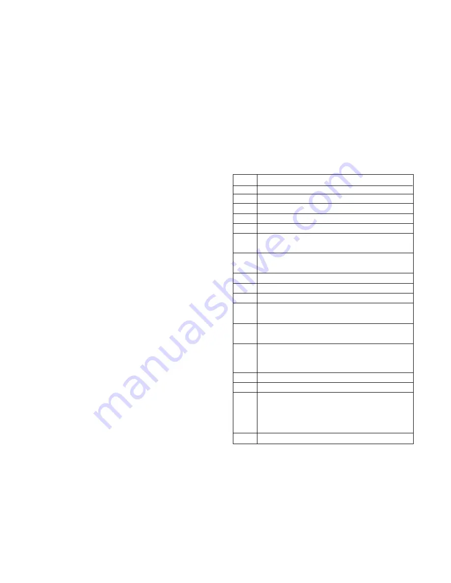
4-3. Checking Error Codes

When the LCD panel displays Err, press the LCD operation

"+" button and "-" button (to the right of the MENU button be-

low the LCD) simultaneously to display the error code.

CORD     ERROR

21:

   No ribbon

26:

   Ribbon size and paper size are different

20:

   Other ribbon jam

23:

   End of ribbon

25:

   Timeout detecting start of ribbon

24:

   Ribbon turning during paper ejection (possible

ribbon jam)

31:

   No paper (even with a paper feed operation, the

edge of the paper does not come)

30:

   Other paper jam

32:

   Error measuring length (not regular paper size)

33:

   Paper set in tray differs from paper setting

37:

   L-size paper (89 x 127 mm) ejection operation has

been done, but the eject switch does not turn ON

38:

   Ejection operation has been done, but the eject

switch does not turn ON

1:

   Strove over error (When printing photos, the time

power is applied to the print head exceeds the line

time)

10:

   Head cannot move (two second timer)

15:

   Failure returning head to standby

11:

   Front edge of paper does not pass "paper top

detection sensor" even though the platen drive

motor moves the prescribed number of steps. Top

of paper cannot be detected

100:

   Head abnormally hot

Содержание DVP-P1

Страница 1: ... not deviate from the resistance wattage and voltage ratings shown CAUTION Danger of explosion if battery is incorrectly replaced Replace only with the same or equivalent type recommended by the manufacturer Discard used batteries according to the manufacturer s instructions NOTE 1 Parts order must contain model number part number and description 2 Substitute parts may be supplied as the service p...

Страница 2: ...rom the 5 V created by the D D converter IC 3 3 V is created by a series regulator and 1 9 V is created from that 3 3 V by a series regulator 2 2 Motor driver section IC 951 is a driver for the stepping motor that drives the platen roller If there is an abnormality in the rotation of the stepping motor printing irregularities will occur The stepping motor has 24 V drive IC 952 is the ink ribbon dr...

Страница 3: ... out signal H The markers are placed at the beginning of each print color but the manner in which the marker is set is different for yellow and the other parts magenta cyan OP Since this printer prints in the order of yellow magenta cyan and OP yellow is detected for the starting of printing Therefore the markers and the sensors are positioned so that yellow is detected by sensor 2 and the others ...

Страница 4: ...etection Ink ribbon feed Error check Error check Paper top detection Yellow top detection Print of yellow Paper feed Ink ribbon feed Error check Error check Paper top detection Magenta top detection Print of magenta Paper supply Error message indicate Turn on a LED ...

Страница 5: ...op detection Cyan top detection Paper feed Ink ribbon feed Error check Error check Print of OP Paper top detection OP top detection Error check Print end Paper eject Error message indicate Turn on a LED Error message indicate Turn on a LED Error message indicate Turn on a LED ...

Страница 6: ...6 3 DISASSEMBLY 3 1 REMOVAL OF CABINET AND TRAY PHOTO 1 Two screws 3 x 10 2 Cabinet 3 Three screws 3 x 10 4 Tray photo 5 Two screws 2 6 x 4 6 FPC 7 Shield A 8 FPC 9 Button power A A B B 1 2 3 4 5 6 7 8 9 ...

Страница 7: ...onnectors C CN162 from MC2 board D CN165 from MC5 board E CN164 from MC4 board F CN163 from MC3 board G CN161 from MC1 board MC6 board H CN952 from housing reel motor I CN951 from stepping motor J CN954 from fan motor K CN953 from cam motor 5 CP1 board C C D D E E F F G G H H I I K K J J 1 2 3 5 4 4 4 4 4 4 4 ...

Страница 8: ...3 x 10 4 Holder chassis 5 Four screws 2 6 x 6 6 Cover back 7 Four screws 2 6 x 6 8 Two screws 2 6 x 10 9 Cover USB 10 Two screws 2 6 x 10 11 TB1 board 12 Chassis 13 Two screws 2 6 x 6 14 TB2 board 15 Three screws 2 x 5 16 Guide ink L L M M 1 2 3 4 5 6 7 8 9 10 11 12 13 14 15 16 Compl mechanism ...

Страница 9: ... 9 3 4 BOARD LOCATION TB2 board TB1 board SY1 board CP1 board ...

Страница 10: ...eration button and button to the right of the MENU button below the LCD simultaneously for two seconds or more press the Print button to switch to the ad justment menu mode The LCD panel displays set test 3 Press the LCD operation button one time to switch to the firmware update menu The LCD panel displays set up 4 Press the MENU button to start the firmware update The LCD panel displays f up or h...

Страница 11: ...SE SVF01 EX DVP P1EX ONLY 7001 636 074 0655 ASSY CARTON CASE SVF01 U DVP P1U ONLY 7002 636 072 2415 CUSHION SHEET SVF01 EX 7003 636 072 2422 REINFORCE PAD A SVF01 EX 7004 636 072 2439 REINFORCE PAD B SVF01 EX 9113 636 071 4779 INSTRUCTION MANUAL English French Spanish EXCEPT DVP P1C 9114 636 071 4786 INSTRUCTION MANUAL German Italy DVP P1EX ONLY 9115 636 075 6144 INSTRUCTION MANUAL China DVP P1C O...

Страница 12: ...0 7726 COVER USB SVF01 EX 03601 411 021 1806 SCR S TPG BIN 2 6X10 03800 636 070 7740 GUIDE INK SVF01 EX 03810 411 187 0903 SCR S TPG BIN W 2X5 03900 636 069 9885 SPACER BUTTOM SVF01 EX 04010 636 069 9816 DEC BUTTON POW SVF01 EX 04020 636 069 9717 BUTTON POWER SVF01 EX 05100 636 073 2858 SHIELD A SVF01 EX 05200 636 073 7761 SPACER SHIELD 1 05300 636 073 7778 SPACER SHIELD 2 05400 411 187 0606 SCR S...

Страница 13: ... 636 070 3445 SPRING PINCH ROLLER F 5H000 636 070 3506 SPRING PINCH ROLLER RB 5H100 636 074 5490 SPRING PINCH RELEASE 5M000 636 070 3353 SLIDE LEVER TPH 6C000 636 070 5692 ASSY ROLLER EXIT GEAR 6D000 636 070 2455 BEARING SHAFT L 6E000 412 066 4104 SPECIAL WASHER 2 5X0 5 6F000 636 070 5708 ASSY ROLLER EXIT PULLEY 6G000 636 070 2455 BEARING SHAFT L 6H000 412 066 4104 SPECIAL WASHER 2 5X0 5 6I000 636...

Страница 14: ...074 5490 SPRING PINCH RELEASE 5I000 636 070 5494 COMPL GUIDE PAPER 5J000 636 071 4823 ASSY GEAR CAM 5K000 636 070 2554 CAM MECHANISM L 5L000 636 070 2561 CAM MECHANISM R 6A000 645 061 4859 COMPL MOTOR CAM 6B000 411 027 1305 SCR S TPG BIN 2 6X4 6P100 636 070 2752 GUIDE PAPER EXIT 6P300 411 021 2407 SCR S TPG BIN 2 6X4 6Q000 411 021 2407 SCR S TPG BIN 2 6X4 7A000 636 070 5432 ASSY CHASSIS R N S P 7C...

Страница 15: ...09 505 9509 IC TK11131CS IC151 409 559 3102 IC LR38873A IC153 409 495 2009 IC LM3525MX IC161 409 548 2802 IC LM339P OR 409 564 5306 IC LM339PWR IC162 410 478 2503 IC MC74VHC1G14DF IC163 409 564 5405 IC SN74LVC14APWR IC181 409 564 7003 IC SN74AHCT244PW IC182 409 564 7003 IC SN74AHCT244PW IC521 409 548 7401 IC SPI8002TW IC523 410 478 2503 IC MC74VHC1G14DF IC524 409 561 8102 IC PQ070XH01ZZ IC525 409 ...

Страница 16: ...3 312 6805 CERAMIC 0 1U Z 16V C1803 403 312 6607 CERAMIC 27P J 50V C1804 403 312 6607 CERAMIC 27P J 50V C1805 403 312 6607 CERAMIC 27P J 50V C1899 403 392 0908 CERAMIC 1U K 50V C1903 403 311 4505 CERAMIC 1000P K 50V C1904 403 311 4505 CERAMIC 1000P K 50V C1905 403 311 4505 CERAMIC 1000P K 50V C1906 403 311 4505 CERAMIC 1000P K 50V C1907 403 311 4505 CERAMIC 1000P K 50V C5201 403 379 6701 CERAMIC 1...

Страница 17: ...24 9006 MT GLAZE 10K JA 1 16W R1122 401 224 9006 MT GLAZE 10K JA 1 16W R1201 401 226 1503 MT GLAZE 0 000 ZA 1 16W R1401 401 224 9006 MT GLAZE 10K JA 1 16W R1405 401 224 9006 MT GLAZE 10K JA 1 16W R1407 401 037 5004 MT GLAZE 0 000 ZA 1 10W R1408 401 224 9006 MT GLAZE 10K JA 1 16W R1410 401 224 9006 MT GLAZE 10K JA 1 16W R1412 401 224 9006 MT GLAZE 10K JA 1 16W R1413 401 224 9006 MT GLAZE 10K JA 1 1...

Страница 18: ...1 037 5004 MT GLAZE 0 000 ZA 1 10W R5219 401 037 5004 MT GLAZE 0 000 ZA 1 10W R5220 401 037 5004 MT GLAZE 0 000 ZA 1 10W R5221 401 037 5004 MT GLAZE 0 000 ZA 1 10W R5222 401 261 5108 MT FILM 1 0K DU 1 16W R5223 401 261 4705 MT FILM 680 DU 1 16W R5224 401 261 5108 MT FILM 1 0K DU 1 16W R5225 401 240 8304 MT GLAZE 0 47 JA 1 4W R5226 401 240 8304 MT GLAZE 0 47 JA 1 4W R5227 401 224 9303 MT GLAZE 1K J...

Страница 19: ...E MA111 OR 407 149 0807 DIODE 1SS355 D3014 407 134 8207 DIODE MA111 OR 407 149 0807 DIODE 1SS355 D3015 407 134 8207 DIODE MA111 OR 407 149 0807 DIODE 1SS355 D3016 407 134 8207 DIODE MA111 OR 407 149 0807 DIODE 1SS355 D3017 407 134 8207 DIODE MA111 OR 407 149 0807 DIODE 1SS355 CAPACITORS C3001 403 164 0204 CERAMIC 0 1U Z 25V C3002 403 392 1202 ELECT 47U M 6 3V C3003 403 113 3805 CERAMIC 1000P K 50V...

Страница 20: ...Oct 0 SANYO Electric Co Ltd Osaka Japan ...

Отзывы: