background image

48

RECORDER MENU

SETTINGS

(3) STOP:

Enter the time at which to stop timer recording.

(4) SET:

Setting “ON” enables the entered timer recording 
setting.
Setting “OFF” disables the entered timer recording 
setting.

(5) SAT, DLY:

Use these lines for timer recording spanning more than 
24 hours.

Recording every day, at the same time, with 
the same image quality

Example:
Setting a timer recording for every day from 8:30 to 
18:30 with the same image quality.

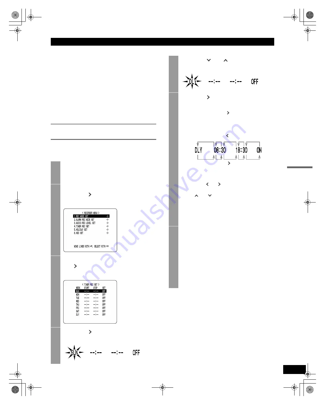
1

Press the [MENU] button.

The [MENU] button lights, and the <MAIN MENU> 
screen is displayed.

2

Select “3. RECORDER MENU”, and 
press the [ ] button.

The <RECORDER MENU> screen is displayed.

3

Select “4. TIMER REC SET” and press 
the [ ] button.

The <TIMER REC SET> screen is displayed.

4

Press the [ ] button once.

“SUN” under “WEEK” flashes.

5

Press the [

] or [

] button to change 

“SUN” to “DLY”.

6

Press the [ ] button to move the 
cursor to the next item.

Each time you press the [ ] button, the cursor 
moves to the following items:
Day   “START” time (hours, minutes)   “STOP” 
time (hours, minutes)   “ON”/“OFF”

„

To change a setting

Press the [ ] or [ ] button to move the flashing 
area to the item you want to change, then press 
the [

] or [

] button to change the setting.

„

Timer recording image quality

The image quality is determined by the 
“PICTURE QUALITY” setting in the <REC MODE 
SET> screen. ( P.44)

7

When you have finished making the 
settings, press the [EXIT/OSD] button.

The display returns to the normal screen.

„

To set different recording times for each 
day of the week

Set the desired recording times for each day.

„

If timer setting days overlap

The timer setting that starts first will have priority.

[ ] button

[ ] button

e00_VDH_M814.book  Page 48  Thursday, October 28, 2004  9:59 AM

Содержание DSR-M814

Страница 1: ...e00_VDH_M814 book Page A Thursday October 28 2004 9 59 AM ...

Страница 2: ...not handle the power cord with wet hands z Do not pull on the power cord when disconnecting it from an AC wall outlet Grasp it by the plug z If any liquid is spilled on the unit unplug the power cord immediately and have the unit inspected at a factory authorised service center z Do not place anything directly on top of this unit SERVICE This unit is a precision instruments and if treated with car...

Страница 3: ...unit pack it securely using the packing materials In addition use a method of transportation that minimizes vibration Notes when replacing the HDD Be sure to follow the correct replacement procedure when replacing the HDD z HDDs that have been removed from their packing may not operate correctly if they are subjected to any shocks and vibration It is recommended that you place HDD onto a soft leve...

Страница 4: ...er has been connected to a wall outlet for at least 48 hours and the date and time have been set the clock function will continue to operate for up to 30 days after the power plug is disconnected When disposing of the digital video recorder contact a Sanyo service center for information on how to dispose of the lithium battery The MENU button is disabled when the unit is connected to a PC VA SW814...

Страница 5: ...g 17 When an alarm input is detected 17 Ending alarm recording 18 3 PLAYING BACK VIDEOS 19 Playback 19 Fast forwarding or rewinding during playback 19 Viewing still images 20 Frame advance reverse 20 Switching audio channels 21 4 SEARCHING FOR RECORDED VIDEOS 22 Alarm search 22 Date and time search 24 5 PREVENTING ACCIDENTAL OPERATION KEY LOCK FUNCTION 26 Setting the key lock function 26 Releasing...

Страница 6: ...ser password 57 Setting the password for recording and playback operations 57 Preventing copying to CD R RWs and CompactFlash cards 58 Setting the security lock 58 8 RS 485 NETWORK SET 59 Network connections and settings 59 RS 485 connections and settings 61 9 POWER LOSS USED TIME 62 10 MENU UPLOAD DOWNLOAD 63 Settings 63 APPENDIX 1 CONTROL TERMINAL SPECIFICATIONS 66 System controller connections ...

Страница 7: ...n allows you to automatically record images containing movements of intruders or others Search function lets you instantly display the desired video P 22 z Search in order of alarm occurrence z Search by date and time Security lock function lets you restrict users for data and equipment management P 55 Expandability and PC connection z The LAN terminal lets you connect the digital video recorder t...

Страница 8: ...6 When the button is pressed while recording or stopped the digital video recorder enters timer record standby and the indicator lights When the set time arrives the digital video recorder starts timer recording 11 ALARM indicator Flashes when recording an alarm image 12 FULL indicator P 44 Lights when the remaining memory in the hard disk s recording area has reached zero and recording has stoppe...

Страница 9: ...lder using the supplied cord tie P 11 7 AC INLET AC power input terminal 3 core 8 TV SYSTEM selector switch Used to select between NTSC and PAL systems for the camera input and monitor output connected to the digital video recorder Disconnect the power and then connect it again after selecting NTSC or PAL 9 RS 485 TERMINATE switch Turns RS 485 termination ON OFF 10 ALL RESET switch Resets the cloc...

Страница 10: ...ion manuals for each connected device Make connections carefully Improper connections can cause smoke or malfunctions The connections for cameras 4 TV monitor 1 microphone and PC are shown below When installing Check the setting Basic connections AUDIO IN 3 4 1 2 OUT LAN 1 1 2 3 4 5 6 7 8 9 10 11 12 13 14 15 16 17 18 19 2 3 4 1 2 3 4 IN OUT MONITOR OUT AC IN VIDEO ALL RESET ON NTSC PAL TV SYSTEM R...

Страница 11: ...ftware VA SW81LITE Ver 2 supplied or VA SW814 Ver 2 sold separately allows you to control all connected DVRs and monitor live video and recorded audio and video from a PC Multiple PCs can also be connected to the network Some functions are not available with VA SW81LITE Ver 2 Connecting to a network SWITCHING HUB SWITCHING HUB SWITCHING HUB SWITCHING HUB SWITCHING HUB PC PC DVR DVR DVR DVR e00_VDH...

Страница 12: ...ller sold separately allows you to set up multiple digital video recorders at the same time P 66 A remote control can be used to perform the operations of the buttons on the front panel To perform remote control operations you must construct your own remote control P 67 Commercially available alarm sensors normal open low level at detection can be connected to the ALARM IN 1 to 4 terminals on the ...

Страница 13: ...34 Shows the month day year 05 10 04 month day year 6 Time display P 34 PLEASE SET THE CLOCK is displayed when you turn the power ON for the first time The digital video recorder uses the date and time to manage recording and playback points 7 Alarm display and alarm count display P 17 When you set an alarm using the ALARM REC MODE SET menu item the alarm display area displays the following inform...

Страница 14: ...mes the normal playback speed X30 30 times the normal playback speed X180 180 times the normal playback speed 1 8 1 8 the normal playback speed 1 4 1 4 the normal playback speed 1 2 1 2 the normal playback speed 2 Image quality display SU SUPER SUP SUPER HI HIGH STD STANDARD 3 Audio recording display A Audio recording ON None Audio recording OFF 4 Remaining time display 000H Displayed in 1 hour in...

Страница 15: ...ingle screens Under the default settings the channel switches automatically every 1 second 2 Press the QUAD SEQUENCE button The quad screen is displayed Displaying the image from a specified channel in a single screen 1 Press the desired CHANNEL button The indicator on the CHANNEL button lights The image for the corresponding channel is displayed in the screen 2 Press the QUAD SEQUENCE button The ...

Страница 16: ...s on the screen and recording starts z When you record for the first time the default settings are used To change the image quality P 43 z When the OVER WRITE recording setting is ON the DVR starts recording from the beginning again When it is OFF and the remaining space reaches zero recording stops and the FULL indicator lights P 44 z You can record and play back images at the same time P 19 z Yo...

Страница 17: ...rmal recording normal and timer recording z After making PICTURE QUALITY or AUDIO RECORDING menu settings and returning to the camera screen recording does not start for a maximum of 6 seconds although normal recording and timer recording operations can be made z After recording finishes the REC STOP indicator turns off recording does not start for a maximum of 10 seconds although normal recording...

Страница 18: ...time is extended counting from that moment The new alarm is not counted and the alarm count remains the same If an alarm is generated on a separate channel the alarm count increases z The 49 999 most recent incidents are stored in the alarm history recording list Older incidents are erased z The camera title generating the alarm flashes z The panel s ALARM indicator flashes Recording upon alarm de...

Страница 19: ... alarm recording 1 After recording starts Standby REC STOP indicator lights 2 After making PICTURE QUALITY or AUDIO RECORDING menu settings and returning to the camera screen For 1 and 2 z Alarm input is not recognized for a maximum of 4 seconds Alarm input after the 4 seconds are recognized as usual z Recording does not start for a maximum of 6 seconds regardless of alarm input 3 After recording ...

Страница 20: ...ghts and appears in the operation display area The videos recorded on the hard disk are played back in the quad screen z Video playback starts from the point at which recording started z If OVER WRITE has been set in the normal recording settings playback starts with the oldest recorded video when the recording is played back for the first time z When playback ends the digital video recorder pause...

Страница 21: ...ed slows to 1 8 the normal speed Pressing the button again switches the playback speed to 1 4 the normal speed Pressing the button twice switches the playback speed to 1 2 the normal speed Slow reverse playback Hold down the button for at least 2 seconds while a still image is displayed The playback speed slows to 1 8 the normal speed Pressing the button again switches the playback speed to 1 4 th...

Страница 22: ...or lights when that channel is playing back During recording During playback During playback you cannot playback audio from one specific channel Switching audio channels STILL button Slow direction Reverse slow direction With still image display Hold down for at least 2 seconds Hold down for at least 2 seconds STILL button AUDIO button CHANNEL indicators CH3 CH4 CH1 CH2 AUTO CH3 CH2 CH4 OFF CH1 CH...

Страница 23: ...ved images being played back 1 ALARM SEARCH Lets you search for and play back alarm recordings 2 TIME DATE SEARCH P 24 Lets you search and play back recorded videos by date and time Lets you search for and play back any alarm recording on the hard disk 1 2 Alarm search 1 Press the SEARCH button while the digital video recorder is recording or stopped The SEARCH screen is displayed continued button...

Страница 24: ...e to play back The selected alarm image is displayed in the preview screen You can list up to 8 alarm recordings z To display the next previous video Press the or button z To display the items on the next page Press the MENU button The next 8 videos are listed chronologically z To end search mode Press the EXIT OSD button 4 Press the button The video is played back on the full screen 1 3 5 4 2 H I...

Страница 25: ...ss the SEARCH button while the digital video recorder is recording or stopped The SEARCH screen is displayed 2 Press the or button to select TIME DATE SEARCH button SEARCH button button button 3 Press the button The TIME DATE SEARCH screen is displayed 1 RECORDING TOP Displays the date and time of the video recorded first 2 RECORDING END Displays the date and time of the video recorded last most r...

Страница 26: ...utton z If no video exists for the specified time The video closest to the selected time is displayed z To end search mode Press the EXIT OSD button 1 2 3 4 5 6 Press the button to select VIEW then press the button The preview screen image is played back in the quad screen z The retrieved video can be displayed in the quad screen format without displaying the preview screen by entering the date an...

Страница 27: ...r lights z The key lock setting is not released at power OFF z You cannot set the key lock during playback Releasing the key lock function With the key lock function set hold down the button for about 3 seconds When the key lock is released a confirmation tone sounds and the LOCK REMOTE indicator turns off z When the key lock function has been set the buttons cannot be used for settings or operati...

Страница 28: ... different discs or cards z At least 2MB of available space is required when copying to a CompactFlash card z The digital video recorder can automatically detect whether the copy destination is a CompactFlash card or a CD R RW disc z Set the security lock setting for COPY TO CD R CF to USE P 55 Connect either a CompactFlash card reader or a CD R RW drive to the USB port on the front of the digital...

Страница 29: ... Press the and buttons to select COPY START and then press the button Copying of video starts When copying has been completed COPY FINISHED appears and the screen will return to the live video display when any button is pressed z A video is copied to the CompactFlash card CD R RW as follows Example Copying from 10 15 on April 25th with a DVR NAME of FRONT 1 A folder is created for the DVR NAME on ...

Страница 30: ...COPY screen appears 2 Press the and buttons to select FORMAT MEDIA and press the button The WARNING screen appears NO flashes 3 Press the and buttons to select YES and press the button Formatting of the media starts When formatting has been completed FORMAT FINISHED appears and press the button to return to the SEARCH COPY screen e00_VDH_M814 book Page 29 Thursday October 28 2004 9 59 AM ...

Страница 31: ... button to select the desired item Example Selecting 5 BUZZER SET When you move the cursor the selected item is displayed in reverse 3 Press the button The setting screen of the selected item is displayed For some items lower level menus can be selected button MENU button button button EXIT OSD button button 4 When you are finished changing the settings press the EXIT OSD button to end The display...

Страница 32: ...Camera titles z Motion sensor for detecting moving subjects 3 RECORDER MENU P 43 Lets you make various recording settings and initialize the hard disk 4 DISPLAY SET P 53 Lets you display or hide information items in the operation display area 5 BUZZER SET P 54 Lets you enable or disable audible alarms for various events 6 SECURITY LOCK SET P 55 Lets you set passwords to prevent unauthorized users ...

Страница 33: ...r failures and the elapsed amount of hard disk operation time 9 MENU UPLOAD DOWNLOAD P 63 Lets you save menu setting values onto a CompactFlash card Also lets you read menu setting values saved on CompactFlash cards Formats CompactFlash cards e00_VDH_M814 book Page 32 Thursday October 28 2004 9 59 AM ...

Страница 34: ...N MENU screen is displayed MAIN MENU button MENU button button button EXIT OSD button 2 Select 1 LANGUAGE CLOCK SET and press the button The LANGUAGE LANGUE IDIOMA screen is displayed Setting Description ENGLISH Sets the language to English FRANCAIS Sets the language to French ESPAÑOL Sets the language to Spanish 3 Press the button then the or button to select the desired language The set item fla...

Страница 35: ...rsor to the date and time under CLOCK SET MONTH DAY YEAR WEEK TIME 4 Press the button 01 indicating the month flashes 5 Press the or button to select 05 6 Press the button 01 indicating the day flashes 7 Use the same procedure to set the day 10 in this example year 2004 hour 08 and minutes 30 z WEEK is set automatically z The time is stopped during clock setting 8 Press the EXIT OSD button The dis...

Страница 36: ...rd time 1 Sets the week for switching to Daylight Saving time 2 Sets the day of the week 3 Sets the month 4 Sets the time 5 Sets the week for ending Daylight Saving time 6 Sets the day of the week 7 Sets the month 8 Sets the time 3 Press the or button to select MODE under DAYLIGHT SAVING 4 Press the button USE flashes 5 Press the or button to change the setting Setting Description USE Time is auto...

Страница 37: ... the desired time then press the button Set the desired minutes in the same manner The DAYLIGHT SAVING settings are now finished Synchronizing the time with other DSR M814 DVRs with two or more DVRs connected 1 Use a cable to connect the CLOCK ADJ OUT terminal on the rear panel of one digital video recorder to the CLOCK ADJ IN terminal on the second digital video recorder Terminal number 6 CLOCK A...

Страница 38: ...returns to the normal screen When the digital video recorder is connected to a PC or other external device through a network you can also set the time from that device When connected to a PC see the instructions for the VA SW814 Ver 2 VA SW81LITE Ver 2 software z Subsequent digital video recorders must be synchronized with the first unit for ADJUST TIME z Do not use a loop connection Set the time ...

Страница 39: ...ing alarm recording Example 1 Display screens in order of alarms Example 2 Display alarm recordings on the single screen sequentially z MASK SET is used to hide the monitor display of some channel images in the normal screen and playback screen TITLE SET z Lets you set titles for the cameras MAIN MENU SUB MENU Screen settings H I A 05 10 04 08 30 35 AL 00015 HI A 05 10 04 08 30 35 AL 00015 HI A 05...

Страница 40: ... units 1SEC Sets time interval used for switching screens when displaying image from each channel sequentially 2 DISPLAY FULL When alarm occurs displays image from channel that generated alarm in single screen QUAD When alarm occurs displays images in quad screen 3 ALARM PRIORITY LAST Displays alarm images in order starting with the most recent when multiple alarms are generated FIRST Displays the...

Страница 41: ...A Number Default value CAMERA NO 1 1 CAMERA NO 2 2 CAMERA NO 3 3 CAMERA NO 4 4 button MENU button button button EXIT OSD button CHANNEL buttons Camera Number 4 Press the desired CHANNEL button to select the desired camera number 5 Press the button to enter text 6 Press the or button to start entering the camera title You can enter up to 10 characters symbols Each time you press the or button the d...

Страница 42: ...t 2 SCREEN SET MENU and press the button The SCREEN SET MENU screen is displayed FLOOR 1 2 Set camera title H I A 0 5 1 0 0 4 0 8 3 0 35AL 0 0 0 1 5 button MENU button button button EXIT OSD button CHANNEL buttons button 3 Select 3 MOTION SENSOR SET and press the button The motion sensor setting screen for CAMERA NO 1 appears 4 Press the desired CHANNEL button to select the desired camera number 5...

Страница 43: ... Setting sensor operation positions Pressing the or button once enables the currently selected position displays Pressing the or button again disables the setting displays Operation position setting example If you set an area near the center of the screen the sensor operates and recording starts when a moving subject near the center of the screen is detected LEVEL Set sensor position Setting examp...

Страница 44: ...ording settings 2 ALARM REC MODE SET z Turns alarm recording ON OFF z Sets the amount of time to record for when an alarm is generated z Sets alarm trigger z Sets the operation to perform when the camera image is interrupted 3 AUDIO REC LEVEL SET Sets audio level for each channel 4 TIMER REC SET Sets timer recording 5 HOLIDAY SET Lets you set specific days other than Sundays as holidays 6 HDD SET ...

Страница 45: ...ideos OFF When the hard disk runs out of space the FULL indicator lights and recording stops 5 DISK FULL RESET NO Does not overwrite The WARNING screen is displayed and NO flashes YES Videos can be recorded over previously recorded videos once The WARNING screen is displayed Press the or button to select YES 6 SERIES REC OFF Does not perform series recording 1M When multiple digital video recorder...

Страница 46: ... screen is displayed 4 Press the or button to select DISK FULL RESET then press the button The WARNING screen is displayed with NO flashing 5 Press the or button to select YES then press the button The normal screen is displayed and the FULL indicator turns off The DVR is ready to record again e00_VDH_M814 book Page 45 Thursday October 28 2004 9 59 AM ...

Страница 47: ...r the amount of time set by the timer Does not return to timer recording standby 2 ALARM DURATION Time selections CC 5SEC 10SEC 20SEC 40SEC 1MIN 2MIN 3MIN 4MIN 5MIN 10MIN 15MIN Sets the amount of time for recording when a single alarm is generated 3 ALARM TRIGGER Selects how to detect intruders ALARM Performs alarm recording when an external alarm is generated when a switch is attached to the alar...

Страница 48: ...he display returns to the normal screen Setting the audio level 1 Press the MENU button The MENU button lights and the MAIN MENU screen is displayed 2 Select 3 RECORDER MENU and press the button The RECORDER MENU screen is displayed 3 Press the or button to select 3 AUDIO REC LEVEL SET then press the button The AUDIO REC LEVEL SET screen is displayed 4 Select the channel and change the audio level...

Страница 49: ...ton once SUN under WEEK flashes 5 Press the or button to change SUN to DLY 6 Press the button to move the cursor to the next item Each time you press the button the cursor moves to the following items Day START time hours minutes STOP time hours minutes ON OFF To change a setting Press the or button to move the flashing area to the item you want to change then press the or button to change the set...

Страница 50: ...MENU screen is displayed 3 Select 4 TIMER REC SET and press the button The TIMER REC SET screen is displayed 4 With the TIMER REC SET screen displayed press the MENU RESET button All the timer settings are erased MENU RESET button 1 Press the MENU button The MENU button lights and the MAIN MENU screen is displayed 2 Select 3 RECORDER MENU and press the button The RECORDER MENU screen is displayed ...

Страница 51: ...ress the or button to change the STOP time from to then press the button The DLY item on line 8 automatically changes to TUE the next day and flashes Items that do not need to be set are displayed as asterisks 7 Set the end WEEK and STOP time Switch SET to ON 1 Press the or button to change TUE to WED then press the button 2 Press the or button to change to 20 then press the button 3 Press the or ...

Страница 52: ...o 2 6 Press the EXIT OSD button The display returns to the normal screen No the month the day Initializing the hard disk adding a hard disk 1 Press the MENU button The MENU button lights and the MAIN MENU screen is displayed 2 Select 3 RECORDER MENU and press the button The RECORDER MENU screen is displayed 3 Press the or button to select 6 HDD SET then press the button The HDD SET screen is displ...

Страница 53: ...mages on both hard disks by setting MIRRORING to ON If an image write error occurs on one disk you will still be able to read the image from the other disk z Playback disk When mirroring is set the digital video recorder automatically sets which of the two hard disks to read the recorded image from 4 Press the button The WARNING screen is displayed with NO flashing 5 Press the or button to select ...

Страница 54: ...a OFF Turns off display of current alarm count in operation display area 4 CAMERA TITLE ON Turns on display of camera title on the screen OFF Turns off display of camera title on the screen MAIN MENU 1 2 3 4 REC H I A 0 5 1 0 0 4 0 8 3 0 3 5 AL 0 0 0 1 5 2 1 4 3 Customizing the operation display area 1 Press the MENU button The MENU button lights and the MAIN MENU screen is displayed 2 Select 4 DI...

Страница 55: ...d 4 WARNING ON Sounds buzzer in following cases z Hard disk drive error z Fan error z Recording error OFF Does not sound buzzer in following cases z Hard disk drive error z Fan error z Recording error 5 NON REC ON Sounds buzzer when recording is stopped OFF Does not sound buzzer when recording is stopped MAIN MENU 1 2 3 4 5 Setting the buzzer for each condition 1 Press the MENU button The MENU but...

Страница 56: ...playback and recording operations Enter the administrator password to enable all operations ADMIN 123456AB ON USER OFF REC CONTROL ADMIN Only playback operations enabled unless password is entered Enter the administrator password to enable all operations ADMIN 123456AB ON USER OFF REC CONTROL USER Only playback and recording operations enabled unless password is entered Enter the administrator pas...

Страница 57: ...B in this example To set a 4 digit password When you have entered four digits and the fifth password entry bar is flashing press the button 7 When you have entered the password press the button The cursor moves to OFF flashing 8 Press the or button to select ON If you select OFF for the ADMIN setting you cannot set the USER password 9 When you have finished making the setting press the button The ...

Страница 58: ...ttings the administrator password to set 123456 6 When you have finished making the setting press the button The cursor moves to OFF which flashes 7 Press the or button to select ON then press the button The cursor moves to REC CONTROL Setting the password for recording and playback operations 3 Press the or button to move the cursor to REC CONTROL 4 Press the button 5 Press the or button to selec...

Страница 59: ...irmation tone sounds the LOCK REMOTE indicator lights and the security lock is set 2 To check the security lock press any button The password entry screen is displayed for about 5 seconds button button button LOCK REMOTE indicator EXIT OSD button MENU button 3 While the password entry screen is displayed enter the password Enter the password using the and buttons Enter the password set for adminis...

Страница 60: ...oftware must be installed on the PC z To connect a PC directly Do not use an Ethernet hub z To connect to an intranet Use an Ethernet hub Settings for connecting to a PC or network This section describes how to set the IP address In the default setting the IP address is set automatically by the PC To set the IP address manually follow the procedures below Network connections and settings Cross cab...

Страница 61: ... the VA SW814 Ver 2 or VA SW81LITE Ver 2 remote control software is used the digital video recorder s STILL button can be pressed to have the IP address set automatically MANUAL The DVR NAME IP ADDRESS and SUB NET MASK are set on the digital video recorder 5 Set DVR NAME IP ADDRESS and SUB NET MASK using the and buttons 6 Press the EXIT OSD button The display returns to the normal screen When a ne...

Страница 62: ...ting Description 1 DATA SPEED 2400 4800 9600 19200 Used to select the communication speed Unit bps 2 STATUS INFO ON Enables status information to be sent on the RS 485 line OFF Not set 3 ALARM INFO ON Enables alarm information to be sent on the RS 485 line OFF Not set 4 ADDRESS 000 to 127 001 When connecting multiple recorders different address numbers are set for each 3 Press the and buttons to s...

Страница 63: ...e of the last 4 power failures and the date time of recovery Displays the date time at which a power failure occurred The number on the left is the number of power failures example 010 This number is reset to 000 after exceeding 999 2 DISK1 USE Displays the total used amount of disk 1 operation time 3 DISK2 USE Displays the total used amount of disk 2 operation time when second disk has been added...

Страница 64: ...see our website at www sanyosecurity com You will need a CompactFlash card reader and CompactFlash card commercially available If COPY MIRRORING SETTINGS is set to YES the hard disk may be initialized If you don t want to initialize the hard disk select NO 1 2 3 4 MAIN MENU button MENU button button button EXIT OSD button button CompactFlash card reader CompactFlash card Settings 1 Press the MENU ...

Страница 65: ...e display returns to the MENU UPLOAD DOWNLOAD screen A file named M814MENU txt is created on the CompactFlash card 1 Press the or button to select LOAD MENUS FROM CF then press the button The WARNING screen is displayed NO flashes 2 Press the or button to select YES then press the button Loading starts When you have finished loading the display returns to the MENU UPLOAD DOWNLOAD screen 1 Press th...

Страница 66: ...rmatting starts When formatting has finished the display returns to the MENU UPLOAD DOWNLOAD screen Formatting a CompactFlash card erases all the data stored on it To cancel formatting select NO Press the EXIT OSD button The display returns to the normal screen e00_VDH_M814 book Page 65 Thursday October 28 2004 9 59 AM ...

Страница 67: ...ol terminal 5 C Common 6 CLOCK ADJ IN Normal open Low level active Input for clock setting 7 CLOCK ADJ OUT Normal resistance 5V DC 57kΩ Low level active Output for clock setting 8 C Common 9 SERIES REC IN Normal open Low level active Input terminal used when recording with multiple digital video recorders connected 10 NON REC OUT SERIES REC OUT Normal resistance 5V DC 57kΩ Low level active Output ...

Страница 68: ...Remote control connections Alarm sensor connections 1 2 3 4 5 6 7 8 9 10 11 12 13 14 15 16 17 18 19 220 220 300 360 470 680 820 1 2k 1 8k 2 2k 3 3k 4 7k 7 5k 13k 27k 68k SW 1 SW 2 SW 3 SW 4 SW 5 SW 6 SW 7 SW 8 SW 9 SW 10 SW 11 SW 12 SW 13 SW 14 SW 15 SW 16 Key Resistance Corresponding button SW1 220 Ω CHANNEL button 1 SW2 440 Ω CHANNEL button 2 SW3 740 Ω CHANNEL button 3 SW4 1100 Ω CHANNEL button ...

Страница 69: ...to ON z Be sure to set the RS 485 termination switches of all devices in between devices other than the first and last devices to OFF If you don t make the correct termination settings data will be distorted and will affect other data making the data transmitted to each device incorrect Example Mode Asynchronous Character length 8 bits Data transmission speed 2400 4800 9600 19200 bps Parity check ...

Страница 70: ...HIFT RP UP 6 SHIFT RP DOWN 7 8 9 SECURITY LOCK ON A PLAY REV PLAY SEARCH DVR SECURITY LOCK OFF B C GROUP SET D GROUP CHECK E GROUP CLEAR F STOP STILL Left digit Right digit 8 9 A B C D E F 0 CAMERA 1 CLOCK ADJUST 1 CAMERA 2 MENU RESET 2 CAMERA 3 3 QUAD CAMERA 4 4 5 6 7 SEQUENCE STATUS SENSE 8 9 CLOCK DOWNLOAD A REC REC DUB REQUEST B FF C REW D E OSD EXIT F STATUS LOG1 REC STOP e00_VDH_M814 book Pa...

Страница 71: ...t terminal 1V p p 75 Ohm unbalanced 4 BNC connectors Video monitor out terminal 1V p p 75 Ohm unbalanced 1 BNC connector Audio input terminal 8 dbs 47 k Ohm unbalanced 4 RCA pin jacks Audio output terminal 8 dbs 600 Ohm unbalanced 1 RCA pin jack Microphone input terminal 60 dbs 10 k Ohm unbalanced 3 5 mm mono jack LAN terminal 100BASE TX RJ 45 USB port For external storage unit CompactFlash card r...

Страница 72: ... fan harness from the clamp During installation After connecting the wire harness to the second hard disk secure each wire harness in place After installation After installing the hard disk secure its power harness in place with the cord holder and reattach the fan harness and connector Dimensions 96 Front Side Cautions when adding a hard disk Connector Clamp Wire harness Cord holder Cord holder C...

Страница 73: ...sp00_VDH_M814 book Page 73 Thursday October 28 2004 10 04 AM ...

Отзывы: