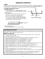
— 9 —
GRAYSCALE ADJUSTMENT
1. Set the picture controls to the Auto levels or Reset (use
MENU key and
▲
or
▼
key or RESET key).
2. Turn off the receiver and disconnect the AC power cord
(120V AC line).
3. While pressing the MENU key, reconnect the AC power
cord. The Service Menu display will now appear.
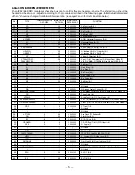
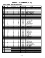
4. Select NO. 49 RB (Red Bias), NO. 4A GB (Green Bias),
and NO. 4B BB (Blue Bias) with
▲
or
▼
key and set each
data to 0 with + or – key.
5. Select NO. 4C RD (Red Drive) and NO. 4E BD (Blue Drive)
with
▲
or
▼
key and set each data to 40 with + or – key.
6. Set NO. 4D GD (Green Drive Reduction) data to 08, NO. 3E
SB (Sub-Brightness) data to 18, NO. 3C SCO (Sub Color)
data to 15, NO. 3D STI (Sub Tint) to 05, and NO. 3F SSH
(Sub Sharpness) data to 00 with
▲
or
▼
, and + or – keys.
7. Turn Screen Control (T402) to minimum (fully counter-
clockwise).
8. Select the Service Menu NO. A9 (No Vertical Sweep)
with
▲
or
▼
key.
9. Advance Screen Control (T402) clockwise to obtain just
visible one color line. If line does not appear, place this
control to maximum (fully clockwise).
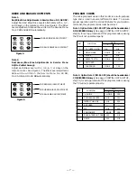
10. Raise each Bias Level with 3, 6, and 9 keys to obtain just
visible white line. See Figure 5.
11. Select the Service Menu NO. A8 DRV (Drive Adjustments)
with
▲
or
▼
key.
12. Adjust Red and Blue Drive Levels alternately with 1, 3,
7, or 9 key to produce normal black and white picture in
highlight areas. See Figure 6.
13. Check for proper grayscale at all brightness levels.
To turn off the Service Menu display, press the MENU key.
Note: If Grayscale Adjustment is made after picture tube
replacement, check Brightness Level Adjustment.
FOCUS ADJUSTMENT
Adjust focus control (T402) for well defined scanning lines.
HIGH VOLTAGE CHECK
Note: +B (+130V) Voltage Check and Grayscale Adjustment
must be completed before attempting high voltage
Check.
1. Connect high voltage voltmeter – lead to ground, and
c lead to anode of picture tube.
2. Tune receiver to an active channel and confirm TV is
operating properly.
3. Eliminate the beam current by adjusting the contrast
and brightness controls to minimum.
4. Confirm high voltage is within 28.0 KV and 31.1 KV. If
reading is not within range, check horizontal circuit.
No high voltage adjustment is provided on this chassis.
BRIGHTNESS LEVEL ADJUSTMENT
Note: Grayscale, RF AGC, Video Level, and High Voltage Check
must be adjusted before attempting Brightness Level
Adjustment.
1. Connect a color-bar generator to the antenna terminals.
2. Switch the generator to the crosshatch pattern.
3. Reset the picture controls to the Auto levels.
4. Connect voltmeter (high impedance) + lead to terminal
TP51 and – lead to terminal TP50 on main board. Set
voltmeter for 1.5V ~ 3V range.
5. Turn off the receiver and disconnect the AC power cord.
6. While pressing the MENU key, reconnect the AC power
cord. The Service Menu display will now appear.
7. Select NO. 3E SB (Sub Brightness) with
▲
or
▼
key.
8. Adjust the data with + or – key for 680mVDC.
9. Press the MENU key to turn off the Service Menu display.
10. Check brightness level on every active channel, readjust
(repeat steps 5 ~ 9), if necessary.
Note: Do not set to excessive brightness level, otherwise
the contrast level will be suppressed.
1
2
3
4
5
6
7
9
8
RB(–)
RB(+)
BB(–)
BB(+)
(N/A)
GB(–)
(N/A)
GB(+)
(N/A)
FOR RED BIAS ADJUSTMENT
FOR BLUE BIAS ADJUSTMENT
FOR GREEN BIAS ADJUSTMENT
Figure 5. Remote Control Number keys’ functions in
Service Menu NO. A9 (No Vertical Sweep)
1
2
3
4
5
6
7
9
8
RD(–)
RD(+)
BD(–)
BD(+)
(N/A)
(N/A)
(N/A)
(N/A)
(N/A)
Figure 6. Remote Control Number keys’ functions in
Service Menu NO. A8 DRV
FOR RED DRIVE ADJUSTMENT
FOR BLUE DRIVE ADJUSTMENT


