— 8 —
SERVICE ADJUSTMENTS (Continued)
VIDEO LEVEL
1. Connect color-bar generator to antenna terminals.
2. Switch the generator to a white field (100 IRE).
3. Set the picture controls to the Auto levels.
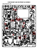
4. Connect oscill lead to terminal TP16 and
– lead to ground.
5. Turn off the receiver and disconnect the AC power cord
(AC 120V line).
6. While pressing the Menu key, reconnect the AC power
cord. The Service Menu will now appear.
7. Select NO. 5F VL5FL (Video Level) with the
▲
or
▼
key.
8. Adjust the data with the 5, 6, and 7 number keys for an
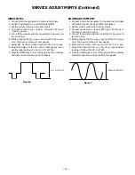
oscilloscope reading of 1.0 ± 0.1 VP-P at TP16.
9 Press the MENU key to turn off the Service Menu display
and disconnect oscilloscope from chassis.
SOUND ADJUSTMENT
1. Connect a color-bar generator to the antenna terminals
with audio signal of 1KHz at 100% modulation.
2. Set the picture controls to the Auto levels.
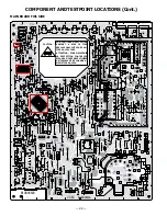
3. Connect oscill lead to TP21 (pin 75 of IC101 or
C132) and – lead to ground.
4. Turn off the receiver and disconnect the AC power cord
(AC 120V line).
5. While pressing the Menu key, reconnect the AC power
cord. The Service Menu will now appear.
6. Select NO. 5F VL5FL (FM Level) with the
▲
or
▼
key.
7. Adjust the data with the + or – key for an oscilloscope
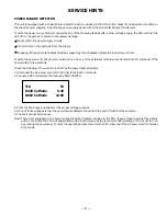
reading of 0.95 ± 10% VP-P at TP21.
8. Press the MENU key to turn off the Service Menu display
and disconnect the oscilloscope from the chassis.
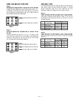
Figure 6.
Figure 7.
1.0 ± 0.1 VP-P
0.95 ± 10% VP-P

