3
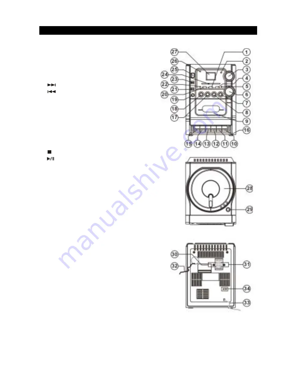
FEATURES AND CONTROLS
1. PROGRAM Button
2. Remote Sensor
3. VOLUME Control
4. REPEAT Button
5. FM Stereo Indicator
6. TUNING Knob
7.
SKIP+ Button
8.
SKIP- Button
9. Cassette Door
10. PAUSE Button
11. STOP / EJECT Button
12. FAST FORWARD Button
13. REWIND Button
14. PLAY Button
15. RECORD Button
16. Cassette Button Door
17.
STOP Button
18.
CD PLAY / PAUSE Button
19. HEADPHONE Jack
20. BASSXPANDER Button
21. BAND Selector (AM / FM / FM ST.)
22. BASSXPANDER Indicator
23. FUNCTION Selector (TAPE / RADIO / CD)
24. Dial Pointer
25. POWER ON / OFF Button
26. POWER Indicator
27. LCD Display
28. CD Door
29. CD Door Open Button
30. RIGHT Speaker Terminal
31. LEFT Speaker Terminal
32. FM Antenna Wire
33. AC Cord
34. VOLTAGE Selector (OPTIONAL)
4
REMOTE CONTROL
1. Infrared
Transmitter
2. RANDOM
Button
3. SKIP+
Button
4. PROG.
Button
5. STOP
Button
6. PLAY / PAUSE Button
7. SKIP-
Button
8. REPEAT
Button
9. Battery
Compartment
INSTALLATION AND CONNECTIONS
REPLACING Remote Control BATTERY
1. Turn over the remote control, and remove the battery door.
2. Install 1 “CR2025” lithium battery according to the polarity diagram on the battery compartment.
3. Close the battery door.
BATTERY PRECAUTIONS
Follow these precautions when using battery in this device:
1. Use only the size and type of battery specified.
2. Be sure to follow the correct polarity when installing the battery as
indicated in the battery compartment. Reversed battery may cause
damage to the device.
3. If the device is not to be used for a long period of time, remove the battery to prevent damage or
injury from possible battery leakage.
4. Do not try to recharge battery, not intended to be recharged; they can overheat and rupture.
(Follow battery manufacturer’s directions.)
SPEAKER CONNECTION
1. Insert the speaker cables by pushing down the terminal lever of the Left
Speaker Terminal and the Right Speaker Terminal.
2. Connect the Left Speaker to Left Speaker Terminals, with white wire to the
L+ and Black wire to the L-.
3. Connect the Right Speaker to Right Speaker Terminals, with white wire to
the R+ and Black wire to the R-.
MAIN CONNECTION
This unit was designed to operate into an AC
230 - 240V
~ 50Hz house current.
Connecting this system to any other power supply could result in damage to the unit, which is not
covered by your warranty. If this plug will not fit into your outlet, you should have your outlet
changed by a qualified licensed electrician.
1. Unwind the AC Power Cord on the main unit.
2. Insert the plug into any convenient AC outlet.
Содержание DC-AX20
Страница 1: ...14 DC AX20 AU INSTRUCTION MANUAL MICRO STEREO SYSTEM ...
Страница 2: ......
Страница 15: ......
Страница 16: ...13 AU SANYO Electric Co Ltd Osaka Japan ...


