-14-
Service Adjustments
Following adjustments are not required to readjust when replacing the memory IC.
Note: +B (+130V) Voltage Check and Grayscale Adjustment
must be completed before attempting High Voltage Check.
(1) Connect high voltage voltmeter negative lead to
ground, and c lead to anode of picture tube.
(2) Tune receiver to an active channel and confirm TV is
operating properly.
(3) Maximize the beam current by adjusting the contrast
and brightness controls to maximum. Confirm high
voltage is within 24.0 KV and 26.5 KV at maximum
beam current.
(4) Eliminate the beam current by adjusting the contrast
and brightness controls to minimum. Confirm high
voltage does not exceed 28.0 KV at zero beam current.
If reading is not within range, check horizontal circuit.
No high-voltage adjustment is provided on this chassis.
HIGH VOLTAGE CHECK
JP646
JP645
R1001
C107
J1001
R4
45
K1002
K1001
6
JP442
Q432
T431A
J104
D102
J114
TP-M
TP-A
D432
KDY-4
KDY-3
KDY-1
T471A
T471
T471-H4
T471-H7
T471-H12
T471-H10
T471-H1
T471-H2
L441-H2
L441-H1
T471-H11
1
J033
J103
R477
J
05
431
J032
R228
D468
C469
D485
R488
R424
C471
L631
R481
5
Q432-H4
Q432-H5
Q432-H3
Q432-H2
R479
C491
C486
Q432-H1
R423
KQ
R426
R475
D467
L431
L432
D421
R355
C106
C101
R105
R103
D103
J004
JP437
178
R501
R422
OUT
IN
3
1
R1006
J106
C132
X171
J105
06
R486
R485
JW6
D476
VID
AUD
AUD
VID
AUD
C1004
R1007
C1003
C1001
C1002
J1002
R1003
R1002
D448
C449
L441
L441A
L441-H3
C435
C435B
R441
R435
C437
C435A
C435-H3
C435-H2
C435-H1
C441B
C441A
C441
D441
C435-H4
C441-H1
C441-H2
C441-H3
C441-H4
R435A-H1
R435A-H2
J435
C436
C436A
JP436
JP1004
C407
JP1005
J438
T471
FBT
T431
H-DRIVE
TRANS.
H-OUT
E
E
E
E
E
16
10
7
1
1
7
10
16
34
21
KG
A
C250V 4A
F601
IC501
R662-H1
R662-H2
R662
C644
IC501-
R518
R519
C520
C518
R512
D512
J
R525
D683
R687
R686
Q683
R663
C662
Q661A
D634
C634
J401
D682
C517
J513
R243
R510
R511
J504
J502
J506
R872
J0
J808
R642
J687
J2
J688
R664-H2
R664-H1
JW3
JP502
J503
JP683
JP633
JP661
JP646
JP645
R646
JP442
D507
J507
D432
C482
J505
KDY-6
KDY-5
KDY-4
KDY-3
KDY-1
T471
A
T471-H1
T471-H2
L441-H2
L441-H1
R431
R477
C433
Q431
C515
C514
C524
C432
J032
L631
J509
R516
R515
R514
IC501-H
R355
JP501
T611-H16
JW4
C641
J633
D631
C631
JP631
D633
C633
C643
R638
R639
D686
R637
R635
VR631
D685
C685
1AA4B10S0160A
R433
J641
J642
C521
R645
J645
T611-H4
R616
R615
R606
R620
R609
L603
D611
Q614
Q611
L604
C611
R612-H1
R612-H2
R604-H2
R604-H1
Q613-H1
C614
R619
C613
R607
D617
Q612
R613
C612
R603
R604
R612
R611
T611
T611A
J604
T611-H14
C607-H1
C607
C607-H2
C608
D613
R618
D610
J605
L605
KG-3
-2
C628
A
F601B
T611-H2
T611-H10
T611-H7
TP-EE
C610
5
L441
L441A
L441-H3
C4
3
R441
R435
C437
C435-H3
C435-H
2
C4
4
C4
4
D441
C441-H2
C441-H3
C441-H4
R435A-H1
J435
Q661
E
B
D605
C605
D603
-H2
D606
C606
J603
-H1
-H3
-H4
C603
D604
C604
TP-B
R665
J607
Q613
Q613-H2
Q613-H3
R605
R613-H1
R613-H2
C608A
R628
R629
R617
C611A
C629
C
R643
JP
4
C646
D663
J666
D662
R669
J643
CONVERTER
TRANS.
V-OUT
+B ADJ.
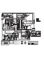
(1) Connect DC meter to TP-B and the ground.
(2) Tune the receiver to an active channel and synchro-
nized picture. Select NATURAL picture mode by press-
ing the PICTURE MODE button on the remote control.
(3) Adjust B-voltage to be 130 ± 1V DC by using VR631.
B-VOLTAGE SUPPLY CHECKING
(1) Receive the monochrome circular pattern.
(2) Set the brightness to normal and contrast to maximum.
(3) Adjust the focus control on the F.B.T. for the best focus
on the screen centre.
FOCUS ADJUSTMENT
MAIN BOARD
B-Voltage Supply Adjustment
Focus VR
(Upper side)
MAIN BOARD
TP-B


