

3
Alignment instructions
1. Test equipment
PM5518 (video signal generator)
VG-849 (VGA and HDMI signal generator)
CA210 (white balancer)
2 Alignment flow-chart
The alignment flow-chart is shown as fig-1
Fig-1 adjustment flow-chart
3 Unit adjustments
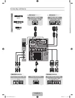
Connect all the boards according to wiring diagram, connect with power and observe the display.
Method for entering factory menu:
press “INPUT”, “2”, “5”, ”8” and “0” in turn to enter factory
menu; press “CH+” and “CH-” to select adjustment items and press “VOL+” and “VOL-” to adjust
value items, press “MENU” continuously to exit.
Method for software upgrading:
enter factory menu and select “OPTION”, set ISP to 1 or insert
jump wire J1, then you can upgrade on line. After upgrade, set ISP back to 0 or pull out jump wire
J1.
3.1 Initialization
Enter factory menu, select “OPTION” and “HOTEL OPTION” sub-menu, adjustment of items to see
table1.
Table1 sub-menu adjustment
Items Preset
Introduce
HOTEL
0
1: HOTEL OPTION of factory menu is optional
0: HOTEL OPTION of factory menu is not optional
LOGO
1
1: display LOGO in no signal or turn on
0: no LOGO display
Check DDC, HDCP KEY, FLASH and POWER control IC
Factory initialization setup
IF channel AFT voltage of TV and AGC voltage
White balance adjustment
Performance check
Preset ex-factory
VGA, YPbPr ADC correction
Содержание AVL-3210
Страница 12: ...10 ...
Страница 14: ...12 ...
Страница 15: ...13 Pin description 1 7 L R input 19 14 L R output 6 10 mute control input ...
Страница 16: ...down up down up down up IF adjustment Wiring diagram 14 ...
Страница 23: ......
Страница 24: ......
Страница 25: ......
Страница 26: ......
Страница 27: ......
Страница 28: ......
Страница 29: ......
Страница 30: ......
Страница 31: ......
Страница 33: ...1 2 3 4 5 6 7 8 9 11 10 AVL3210 ...
Страница 36: ...Mar 2008 ...