
- 2 -
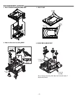
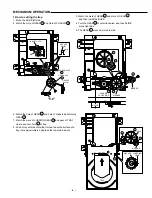
DVD MECHANISM REPLACEMENT
1.Cautionary instructions in handling the assy
(Safety instructions)
Optical pickup
The laser beam used in the pickup is classified as "class 2". Exposing
your eyes or skin to the beam is harmful. Take care not to do so.
(Caution against static electricity and leakage voltage)
Ground securely the work tables, tools, fixtures, soldering irons
(including those made of ceramic) and measuring instruments used
in the production lines and inspection departments that handle
loaders. The workers shall also be grounded.
(Cautionary instructions in handling)
Do not touch the object lens when handling a loader, or the lens will
be stained, resulting in inadequate playability.
There is no power supply protection circuit provided for this product
or adjustment/inspection device. Short-circuiting may lead to fire or
damage.
Take care so as to protect from exposure to water, the entry of
metallic pieces or dew condensation.
In particular, a strong magnet adjacent to the pickup will not only
get inoperative but can damage the pickup if a small metallic piece,
such as a screw or swarm, enters.
The loader edge can cause injury if inadvertently handled.
Do not touch a rotating disk, or injury may result.
This product is a precision device. Handle carefully.
A shock or dropping will cause misalignment or destruction. If it
should occur, refer to clause 2.
This product is so designed as to endure an initial shock equivalent
to a drop from a height of approx. 90 cm under the packed condition.
After the initial shock, the resistivity will still remain at a level of 50
to 60 G, but the mechanical robustness will weaken.
Do not place in a dusty location.
The entry and deposition of dirt into or on the pickup lens or moving
section will cause malfunction or degradation.
(Connectors)
Do not connect or disconnect while power is on.
Connecting or disconnecting signal wires or the main power cord
when the power is on may destruct the unit or fixture.
When connecting, push all the way in securely.
An insufficient insertion may cause a bad contact, leading to an
erroneous operation.
Do not connect or disconnect roughly by an excessively strong force,
or a broken wire or bad contact may result.
Semiconductors are connected. Do not touch connector terminals
directly.
If the worker is grounded, there is nothing to worry about static
electricity, but the rust on the connector terminal surface caused by
the touch may result in bad contact.
(Power source)
The power source need be good in quality (free from instantaneous
interruptions or noises).
A low quality power source may well cause malfunction.
(Storage)
Do not place or store in a dusty place or a place where dew
condensation is possible.
The entry and deposition of dirt or dust into or on the pickup lens or
moving section will cause malfunction or degradation.
Also, dew condensation causes rust;the rust penetrate into the
precision part of a pickup, causing malfunction, or degrading the
optical quality of the internal lens and reflector, which also leads to
malfunction.
Содержание 137 103 01
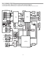
Страница 47: ...SCHEMATIC DIAGRAM MPEG for AU SS and CA This is a basic schematic diagram 64 65 ...
Страница 48: ...SCHEMATIC DIAGRAM MPEG for XE UK This is a basic schematic diagram 66 67 ...
Страница 53: ...SANYO Technosound Co Ltd Osaka Japan Apr 01 3500 BB Printed in Japan ...
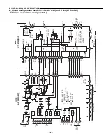
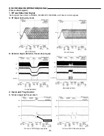
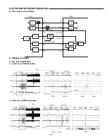
Страница 55: ...DVD P W BOARD OPERATION SCHEMATIC DIAGRAM FOR SIGNAL CHECK for top left This is a basic signal check 10 11 ...
Страница 56: ...DVD P W BOARD OPERATION SCHEMATIC DIAGRAM FOR SIGNAL CHECK for top right This is a basic signal check 12 13 ...
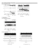
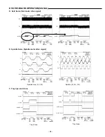
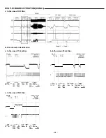
Страница 57: ...DVD P W BOARD OPERATION SCHEMATIC DIAGRAM FOR SIGNAL CHECK for bottom left This is a basic signal check 14 15 ...
Страница 58: ...DVD P W BOARD OPERATION SCHEMATIC DIAGRAM FOR SIGNAL CHECK for bottom right This is a basic signal check 16 17 ...
Страница 59: ... 18 DVD P W BOARD OPERATION WIRING DIAGRAM FOR SIGNAL CHECK A A side This is a basic signal check ...
Страница 60: ... 19 DVD P W BOARD OPERATION WIRING DIAGRAM FOR SIGNAL CHECK B B side This is a basic signal check ...
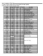
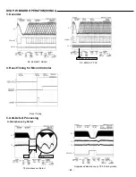
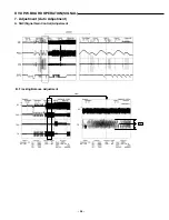
Страница 61: ...MPEG P W BOARD SCHEMATIC DIAGRAM FOR WAVEFORM CHECK This is a basic waveform check 32 33 ...
Страница 62: ...AMP P W BOARD SCHEMATIC DIAGRAM FOR WAVEFORM CHECK This is a basic waveform check 34 35 ...
Страница 63: ...WIRING DIAGRAM MPEG A SIDE 68 69 ...
Страница 64: ...WIRING DIAGRAM MPEG B SIDE 70 71 ...
Страница 65: ...WIRING DIAGRAM DG SOCKET POWER SW for AU SS 74 75 DG SOCKET POWER SW ...
Страница 66: ...WIRING DIAGRAM FRONT for AU SS 76 77 ...
Страница 67: ...WIRING DIAGRAM DG SOCKET POWER SW for XE UK 80 81 DG SOCKET POWER SW SCART SW ...
Страница 68: ...WIRING DIAGRAM FRONT for XE UK 82 83 ...
Страница 69: ...WIRING DIAGRAM DG SOCKET POWER SW for CA 86 87 DG SOCKET POWER SW ...
Страница 70: ...WIRING DIAGRAM FRONT for CA 88 89 ...
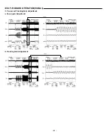
Страница 72: ...SCHEMATIC DIAGRAM DVD TOP LEFT This is a basic schematic diagram 92 93 ...
Страница 73: ...SCHEMATIC DIAGRAM DVD BOTTOM LEFT This is a basic schematic diagram 94 95 ...
Страница 74: ...SCHEMATIC DIAGRAM DVD TOP RIGHT This is a basic schematic diagram 96 97 ...
Страница 75: ...SCHEMATIC DIAGRAM DVD BOTTOM RIGHT This is a basic schematic diagram 98 99 ...
Страница 76: ... 100 WIRING DIAGRAM DVD A SIDE ...
Страница 77: ... 101 WIRING DIAGRAM DVD B SIDE ...


