− 38 −
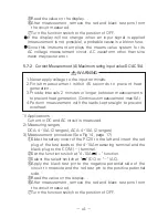
③
Select the select switch at "
".
④
Apply the black test pin to the cathode of the diode and the red
test pin to the anode.
⑤
Make sure that the display shows a diode forward voltage drop.
⑥
Replace the red and black test pins, make sure that the display
is the same as that when the test leads are released.
⑦
After measurement, release the red and black test pins from the
object measured.
⑧
Turn the function switch to the position of OFF.
Judgement
When the items
⑤
and
⑥
are normal, the diode is good.
The input terminals release voltage is about 1.5V.
5-5 Checking Continuity ( )
Never apply voltage to the input terminals.
WARNING
1) Application
Checking the continuity of wiring and selecting wires.
2) Measurement procedure (See Fig 10, page 13)
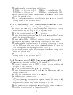
①
Connect the black plug of the test lead to the COM
input
terminal and the red plug to the
input terminal.
②
Set the function switch at "
Ω
/
/
" function.
③
Select the select switch at "
" .
④
Apply the red and black test pins to a circuit or conductor to measure.
⑤
The continuity can be judged by whether the buzzer sounds or not.
⑥
After measurement, release the red and black test pins from the
object measured.
⑦
Turn the function switch to the position of OFF.
The buzzer sounds when the resistance in a circuit to measure is
less than 10
120
Ω
.
Even if the buzzer does not sound, a resistance value up to 10
120
Ω
will be displayed.
The input terminals release voltage is about 0.4V.
The buzzer will not sound if the incorporated battery is removed form the
PC20 and it is operated with the power supply of the AC adapter only.
Содержание PC20
Страница 1: ...PC20 DIGITAL MULTIMETER 取扱説明書 INSTRUCTION MANUAL ...
Страница 2: ......

