background image

3

6901-100015 <01>

1

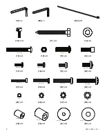
Determine the Bolt diameter required — [17] / [21], [18] / [22], [19] / [23], or [20]/ [24] — by threading each size into the back of 
the TV. Stop immediately if you encounter any resistance.

1-1: TV with flat back

1-2: TV with curved back or obstruction

[05]

M4 x 12mm

M5 x 12mm

M6 x 12mm

M8 x 16mm

[31]

[26]

[18]

[31]

[25]

[17]

[32]

[27]

[19]

[32]

[28]

[20]

M4 x 30mm

M6 x 35mm

M8 x 40mm

M5 x 30mm

[31] [26] [22]

[31] [25] [21]

[32] [27] [23]

[32] [28] [24]

[31]

[31]

[—]

[—]

[05]

[29]

[29]

[30]

[30]

4x

1-1

1-2

Содержание VisionMount VMDD26

Страница 1: ...lb or 1600 cm 63 in The wall must support five times the weight of the TV plus the wall mount If necessary reinforce the structure before installing the unit Failure to provide adequate structural strength may result in serious personal injury or damage to equipment The supplied wall mounting hardware is not for metal stud concrete brick or block walls If you are uncertain about the nature of your...

Страница 2: ... 12mm M6 M8 M4 M5 M6 M8 M4 M5 5 16 in 1 4 20 1 4 20 x 2 0 in M8 x 40mm 5 16 18 x 1 in M5 M4 M6 M8 07 x 1 08 x 1 09 x 20 10 x 14 11 x 4 12 x 4 13 x 4 14 x 4 15 x 3 16 x 4 17 x 4 18 x 4 19 x 4 20 x 4 21 x 4 22 x 4 23 x 4 24 x 4 25 x 4 26 x 4 27 x 4 28 x 4 29 x 4 30 x 4 31 x 8 32 x 4 ...

Страница 3: ...to the back of the TV Stop immediately if you encounter any resistance 1 1 TV with flat back 1 2 TV with curved back or obstruction 05 M4 x 12mm M5 x 12mm M6 x 12mm 31 26 18 31 25 17 32 27 19 32 28 20 M4 x 30mm M6 x 35mm M8 x 40mm M5 x 30mm 31 26 22 31 25 21 32 27 23 32 28 24 31 31 05 29 29 30 30 4x 1 1 1 2 ...

Страница 4: ... 6901 100015 01 2 Do not overtighten the Nut 14 The Vise Assembly 06 should rotate freely around the Carriage Bolt 13 04 06 13 05 06 05 04 3 4x 2x 14 ...

Страница 5: ...on Vise Assemblies 06 and A of the Arm Assembly 02 Do not overtighten Vise Assemblies 06 and A Turn the Allen Bolt until resistance is felt Then tighten the Bolt about 1 turns or until it is slightly above the surface of the Vice Assembly The Tubes 04 will not move from side to side if the Vise Assemblies are correctly tightened 04 02 05 06 06 06 A A 5 3 16 in 305 mm 12 in 4x 4x 63 5 mm 2 5 in ...

Страница 6: ...ach Lag Bolt 11 only until the Wall Plate 01 is pulled firmly against the wall The drywall or other wall material may not exceed 15 8 mm 5 8 in in thickness 4x 7 caution To prevent property damage or personal injury all Safety Bolts 15 must be securely tightened 15 3x 02 01 01 11 12 ...

Страница 7: ...e Tension Nuts T For the Tension Nuts closest to the TV remove the Safety Bracket S adjust the tension and reinstall the Safety Bracket 8 Set the tilt tension with the Knobs K on the Arm Assembly 02 The TV freely tilts 5 to 15 without further Knob adjustment To change the roll 6 loosen the Allen Bolts B on the Arm Assembly position the TV and retighten the Allen Bolts K B 02 02 T T T S 02 ...

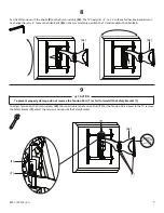
Страница 8: ...akes no representation of warranty expressed or implied regarding the information contained herein CSAV assumes no responsibility for accuracy completeness or sufficiency of the information contained in this document 10 CAUTION To avoid injury do not place your hands or fingers between moveable parts 03 16 11 Leave some slack in the cables to prevent excess tension on the connectors Do not run cab...

Отзывы: