


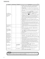

Preparation Before Operation
26
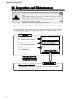
Buzzer: Beep-beep, beep-beep, beep-beep…
After 5 seconds elapse, the state becomes as shown below.
Buzzer: Stopped
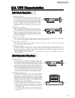
When the UPS is working properly, the buzzer sound, LCD display, and LED state will be as
indicated in steps 5 and 6.
OFF
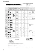
⑤
Set
MAIN MCCB
on any one UPS unit to “OFF.”
⑥
Set
MAIN MCCB
on the UPS unit operated in step 5 to “ON.”
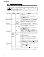
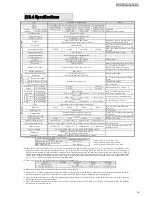
Check the possible causes and counter measures in the table below, and then conduct the power outage simulation test
again from step 1.
Possible Cause
Countermeasure
Is the forced bypass switch
Forced
Bypass
set to
the “
Bypass
” side?
Set the switch to the “
Inverter
” side.
⇒
Step 8 of §6.2 “Installing UPS”
Are the cables connected to the back of the UPS
properly?
Connect the cables properly.
⇒
§6.3 “Connection Between Units”
Is “Green OUTPUT” off?
Perform the ON operation properly.
⇒
Steps 2 and 3 of §7.3 “Power Outage Simulation Test”
Are “Red ALARM” and “Red WARNING” light?
Contact your supplier or SANYO DENKI.
Contact your supplier or SANYO DENKI when “Red ALARM” and “Red WARNING” light or when the UPS
does not operate properly even if you perform the corresponding countermeasure above.
This completes the power outage simulation test.
When the power outage simulation test does not finish properly
Green: Lit
Green: Blinking
Green: Lit
Red: Off
Green: Blinking Green: Lit Red: Off
Green: Lit
Green: Lit
Red: Off
Green: Lit Green: Off Red: Off
‑ ONLINE
****
‑ BATTERY
****
Green: Lit
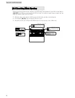
⑦
Check that the all UPS units operate properly.
The state of the LEDs of all
UPS units becomes the same.
The state of the LEDs of all
UPS units becomes the same
.
Set
MAIN MCCB
on any
one UPS unit to “OFF.”
Set
MAIN MCCB
on the
UPS unit operated in
step 5 to “ON.”
Содержание A11J S2
Страница 1: ...M0009239 TYPE S2 5 10 15 20 kVA Instruction Manual...
Страница 25: ...Installation and Wiring 22 Blank page...


