background image

KBox B-201-CFL -  User Guide, Rev 1.3 


www.kontron.com 


// 25 


4.4.


Top Cover and Bottom Side Features 

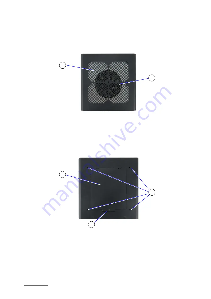
The top cover consisting of a metal plate with air-intake ventilation openings with a separate metal plate underneath 
including a circular opening above the internal fan.  

Figure 8: Top View 


1


Ventilation openings (air-intake) 

2


Circular opening on metal plate 

underneath 


The bottom side contains an external 2.5” SSD drive bay that opens or closes using a single screw (Figure 9, pos. 3). 
The four threaded holes (Figure 9, pos. 2 ) enable the KBox B-201-CFL to be mounted on the back of a VESA 100 
compatible monitor using Kontron’s VESA 100 mount assembly, see Chapter 8.4: VESA 100 Mount Assembly (Option). 

Figure 9: Bottom View  


1


2.5” SSD drive bay cover 

2


4 x threaded holes for VESA 100 
mount assembly 

3


2.5” SSD drive bay cover screw (opens 

and closes 2.5” SSD drive bay) 


Содержание Kontron B Series

Страница 1: ...USER GUIDE www kontron com 1 KBox B 201 CFL Doc User Guide Rev 1 3 Doc ID 1065 0689...

Страница 2: ...KBox B 201 CFL User Guide Rev 1 3 www kontron com 2 This page has been intentionally left blank...

Страница 3: ...be suitable for the specified use without further testing or modification Kontron expressly informs the user that this user guide only contains a general description of processes and instructions whi...

Страница 4: ...use or resale THIS PRODUCT IS NOT DESIGNED MANUFACTURED OR INTENDED FOR USE OR RESALE FOR THE OPERATION OF APPLICATION IN A HAZARDOUS ENVIRONMENT OR REQUIRING FAIL SAFE PERFORMANCE OR IN WHICH THE FA...

Страница 5: ...erms Conditions Visit http www kontron com terms and conditions For contact information refer to the corporate offices contact information on the last page of this user guide or visit our website CONT...

Страница 6: ...escribed by the law may endanger your life health and or result in damage to your material ESD Sensitive Device This symbol and title inform that the electronic boards and their components are sensiti...

Страница 7: ...he earth ground cable shall be the last cable to be disconnected or the first cable to be connected when performing installation or removal procedures on this product Special Handling and Unpacking In...

Страница 8: ...en re pack it in the same manner as it was delivered Special care is necessary when handling or unpacking the product See Special Handling and Unpacking Instruction Quality and Environmental Managemen...

Страница 9: ...ies 16 3 5 Product Identification Type Label 17 4 Product Features 18 4 1 Front Side Features 19 4 1 1 Front Connectors and Buttons 19 4 2 Rear Side Features 20 4 2 1 Rear Panel Connectors 21 4 3 Left...

Страница 10: ...10 3 2 Dimension Diagrams Wall Mount Brackets 56 10 4 Environmental Specification 56 10 5 Directives and Standards 56 10 6 Power Specification 58 10 6 1 12 VDC 58 10 6 2 24 VDC optional variant 58 10...

Страница 11: ...ype A Pin Assignment 60 Table 17 USB 2 0 Connector Pin Assignment 61 Table 18 LAN GbE Connector Pin Assignment 61 Table 19 LAN Link Activity 61 Table 20 Display Port DP Connector Pin Assignment 62 Tab...

Страница 12: ...Assembly Kit 42 Figure 28 KBox B 201 CFL Mounting Position 42 Figure 29 Inserting the Band 43 Figure 30 Positioning the Power Supply 43 Figure 31 KBox B 201 CFL and Power Supply Mounting Position 43...

Страница 13: ...connected to the product s available interfaces I O Before opening the product make sure that the product is disconnected from the mains Switching off the product by its power button does not disconn...

Страница 14: ...erial Always wear a wrist strap connected to workplace Always use properly grounded tools and equipment 2 Use antistatic mats heel straps or air ionizers for more protection 3 Always handle electrosta...

Страница 15: ...a robust metal chassis that guarantees flexibility in multiple user applications such as behind a monitor horizontal and vertical wall mounting or as a movable or fixed desktop version Figure 1 KBox...

Страница 16: ...tions are contained within this user guide and available as a download from the product s web page Table 1 Scope of Delivery Product Description KBox B 201 CFL Smart 12 VDC 1x KBox B 201 CFL with D363...

Страница 17: ...contains specific product information Model Power Product Number Serial Number Electrical Specification and Compliance Figure 2 Type Label 1 Product Family KBoxB 201 CFL 2 Electrical Specification 12...

Страница 18: ...w kontron com 18 4 Product Features Before working with the KBox B 201 CFL Kontron recommends that users take a few minutes to study this chapter and learn about the product s various parts and featur...

Страница 19: ...des an integrated power LED that lights up blue to indicate the powered on state By pressing the power on button for longer than four seconds initiates a forced system shutdown before switching off th...

Страница 20: ...s support different rear panel I O interfaces see Figure 5 and Figure 6 Figure 5 Rear Panel KBox B 201 CFL Smart 1 PS 2 Keyboard 2 PS 2 Mouse 3 4x USB 2 0 4 2x DP 5 Serial port 6 DVI D 7 2x LAN GbE 8...

Страница 21: ...2 Keyboard The PS 2 Keyboard connector purple enables the connection of a keyboard For the pin assignment see Chapter 11 7 PS 2 Keyboard Connector Pin Assignment 4 2 1 2 PS 2 Mouse The PS 2 mouse conn...

Страница 22: ...he DVI D connector supports single link only and enables the connection of a digital display using the DVI D 24 pin female connector directly or with an adapter For the pin assignment see Chapter 11 6...

Страница 23: ...signals are selectable in the BIOS setup menus For the pin assignment see Chapter 11 9 Audio Line out and Audio Line in Connector Pin Assignment 4 2 1 11 DC IN The DC IN power jack connects to the sup...

Страница 24: ...two threaded screw holes available on both sides Figure 7 pos 2 are used to attach the mounting brackets see Chapter 8 3 Mounting Brackets Option or alternatively to attach the vertical stand see Chap...

Страница 25: ...ening on metal plate underneath The bottom side contains an external 2 5 SSD drive bay that opens or closes using a single screw Figure 9 pos 3 The four threaded holes Figure 9 pos 2 enable the KBox B...

Страница 26: ...Value variant with optional Wi Fi is delivered with the mPCIe socket populate with a half size mPCIe card This must be taken into consideration when adding M 2 modules 5 2 1 mPCIE Socket The onboard...

Страница 27: ...sed SSD NVMW modules 2x PCIe Gen 2 lanes No support for SATA based M 2 modules HDD Password support for disk drives and M 2 SSD module access protection When expanding the KBox B 201 CFL with a M 2 mo...

Страница 28: ...nd fulfills all necessary technical and environmental requirements Please follow the safety instructions for components that are sensitive to electrostatic discharge ESD Failure to observe this warnin...

Страница 29: ...side the top cover off the chassis Do not slide the top cover off the chassis Avoid contact and possible damage between the top cover and the internal fan assembly by moving the top cover when release...

Страница 30: ...ing a torx screwdriver 08 x 60 Figure 9 pos 3 4 Lift the SSD drive bay cover a few centimeters to release the SSD from the internal SSD holding plate on the rear side of the SSD drive bay cover Figure...

Страница 31: ...and Closing SSD Drive Bay Cover step 7 After installing or removing a 2 5 SSD the partitioning of the memory maybe different To remove a 2 5 SSD perform the following 1 Open the SSD drive bay cover by...

Страница 32: ...o 5 2 Locate the installed M 2 module 3 Remove the M3x4 screw The M 2 module springs up at the free end 4 Gently pull the M 2 module out of the M 2 socket 5 Close the Chassis as described in Chapter 6...

Страница 33: ...Opening and Closing the Chassis opening procedure steps 1 to 5 2 Locate the installed mPCIe card 3 Remove the mountings screw and spacer and the mPCIe card springs up at the free end 4 Gently pull ou...

Страница 34: ...2 and 3 Obstructing the ventilation openings may cause overheating Do not to place items directly in front of the top cover ventilation openings and observed that all ventilation openings are not cov...

Страница 35: ...ve been taken into consideration Leave sufficient clearance keep out area to prevent the product from overheating To ensure proper operation use the specified recommended keep out areas of Top cover 1...

Страница 36: ...voltage feeds must not be overloaded Adjust the cabling and the overcurrent protection to correspond with the electrical specification on the type label Kontron recommends that the last cable attache...

Страница 37: ...re 17 Position of Chassis Feet To improve stability positioning chassis feet between the mounting hole and the outside edge 8 1 1 Chassis Feet Mount Option The KBox B 201 CFL with chassis feet can be...

Страница 38: ...rds 2 Aline the two vertical stand screw holes with the two threaded screw holes on the side of the chassis 3 Using a torx 08 x60 screwdriver and the screws provided with the stand fasten the stand to...

Страница 39: ...enings are not covered or obstructed by objects Leave sufficient clearance keep out area to prevent the device from possibly overheating To ensure proper operation use the specified recommended keep o...

Страница 40: ...ling the dual Wi Fi antennas on the rear panel increases the keep out clearance to 45 mm and 130 mm from Wi Fi hinge Keep Out Areas front rear panel and right left sides Keep Out Areas top cover right...

Страница 41: ...d risk of fire observe the following DO NOT mount horizontally with the top cover facing downward Only use the allowed mount orientations Horizontally with top cover facing upwards Vertically all poss...

Страница 42: ...ame perform the following 1 Check if chassis feet are installed on the bottom side of the chassis If feet are installed removed the feet before mounting on the VESA 100 mounting frame 2 Align the four...

Страница 43: ...Figure 30 Positioning the Power Supply 6 Slot the power supply with the 3 pin AC connector facing towards the bottom of the VESA 100 mounting frame into the gap made in step 5 and feed the power supp...

Страница 44: ...ing is possible 8 4 1 1 Mounting on non VESA Mount Stand Monitor 1 Feed the four supplied M4x 20 mm screws through the four mount hole on the VESA mount frame and attach one of the supplied spacers on...

Страница 45: ...to the screw s free end Figure 34 Figure 34 VESA Monitor Stand Assembly 3 First insert the free end of the screw with spacer through the four mount hole on the VESA mount frame and then onto the VESA...

Страница 46: ...ng the Wi Fi antenna increases the original keep out area on the rear side from 10 mm to approximately 45 mm To install the Wi Fi antenna perform the following 1 Screw the Wi Fi antenna on to the Wi F...

Страница 47: ...9 1 1 12 VDC AC DC Power Supply The KBoxB 201 CFL Smart or Value standard variant is powered using the supplied 12 VDC external AC DC power supply To connect the external AC DC power supply perform th...

Страница 48: ...I O connections on the rear side are firmly connected 3 Check that the top cover and SSD drive bay cover are secured 4 Screw the 24 VDC power cable Figure 36 pos 1 to the DC IN power jack Figure 5 po...

Страница 49: ...ystem shutdown before switching off the power If power is still applied to the DC IN connector the product can be restarted by pressing the power on button Do not disconnect the power from the product...

Страница 50: ...ard Chipset Onboard connectors External interfaces CPU Onboard memory Dual Channel DDR4 2666 UDIMM up to 32 GB 4x USB 2 0 2x LAN GbE DVI D 2x DisplayPort Mouse PS 2 Keyboard PS 2 Serial Port Audio In...

Страница 51: ...et Onboard connectors External interfaces CPU Dual Channel DDR4 2666 UDIMM up to 32 GB 2x USB 3 1 Gen 1 3x USB 2 0 2x LAN GbE DVI D DisplayPort Mouse PS 2 Keyboard PS 2 Serial Port Audio In Out DC IN...

Страница 52: ...tel UHD Graphic 630 Intel UHD Graphic 630 Processor Type 9th Gen Intel i3 9100E Intel i5 9500E Intel i7 9700E Core 4 6 8 Cache 6 MB Smart cache 9 MB Smart cache 12 MB Smart Processor Base Freq 3 1 GHz...

Страница 53: ...RS232 1x COM1 RS232 Audio Line in Line out with HD Audio Line in Line out HD Audio PS 2 Mouse Keyboard Mouse Keyboard DC IN standard 12 VDC 24 VDC variant 12 VDC 24 VDC variant Options Wi Fi Antenna D...

Страница 54: ...l Aluminum grey Cooling Fan cooled axial fan Silent fan Mounting Options Mounting bracket depth x width x height 187 mm x 45 mm x 20 mm 7 36 x 1 77 x 0 79 Vertical stand depth x width x height 187 mm...

Страница 55: ...de Rev 1 3 www kontron com 55 Figure 41 Dimensions Top Cover Figure 42 Dimensions Bottom Side Figure 43 Dimensions Right Side and Left Side 6 5 mm 6 5 mm 190 mm 190 mm 6 5 mm 6 5 mm 130 mm 190 mm 190...

Страница 56: ...a level 1 m Full CPU GPU load Shock Operating Half sine 15 g 11 ms acc to IEC 60068 2 27 Vibration Operating 5 Hz 500 Hz 1 G acc to IEC 60068 2 6 MTBF 62257 hours 40 C based on Telcordia SR 332 Issue...

Страница 57: ...ystems Immunity Industrial Equipment EN 55024 2010 CISPR 24 Edition 2 1 Information technology equipment immunity characteristics Safety Europe EN 62368 1 2014 Audio video information and communicatio...

Страница 58: ...se the AC DC power supply supplied in the delivery and chosen to meet the product s power specification power consumption and power protection requirements Table 11 External AC DC power supply Power S...

Страница 59: ...in the off state long enough to allow internal voltages to discharge sufficiently During the off state time do not disconnect an add cables to from the I O connectors Failure to observe the off state...

Страница 60: ...al Power Jack Centre pole 12 VDC Standard 24 VDC optional variant Outer ring Ground Due to additional internal components in the 24 VDC variant the 12 VDC and optional 24 VDC variant are not interchan...

Страница 61: ...ted by a minus sign 11 4 LAN GbE Connector Pin Assignment Table 18 LAN GbE Connector Pin Assignment Low active signals are indicated by a minus sign Table 19 LAN Link Activity Speed Yellow LINK ACT Gr...

Страница 62: ...detect 18 19 GND return 3 3V fuse protested 20 Low active signals are indicated by a minus sign 11 6 DVI D Connector Pin Assignment Table 21 DVI D Connector Pin Assignment Pin Signal Name Pin Signal N...

Страница 63: ...d Audio Line in Connector Pin Assignment Table 24 Audio Line out Audio Line in Pin Assignment Connector Signal Audio Barrel Connectors Green Line out Blue Line in Supports HD audio and legacy audio se...

Страница 64: ...Serial Interface COM1 port RS232 Connector Pin Assignment Pin Signal Name RS232 Description 9 pin D SUB Connector 1 DCD Data Carrier Detect 1 5 6 9 2 SIN Signal In 3 SOUT Signal out 4 DTR Data Termin...

Страница 65: ...1 Starting the uEFI BIOS The uEFI BIOS comes with a setup program that provides quick and easy access to the individual function settings for control or modification of the uEFI BIOS configuration Th...

Страница 66: ...d or selects a submenu 12 2 BIOS Update To ensure compatibility with new Operating Systems OS hardware or software and to integrate new BIOS functions Kontron recommends updating the BIOS regularly If...

Страница 67: ...form the following 1 Click on BIOS Update Admin Pack 2 Download the Admin Package Compressed Flash files ZIP file from the website to a PC 3 Unzip and copy the file to a FAT32 formatted USB stick 4 Lo...

Страница 68: ...riod Follow these steps before returning any product to Kontron 1 Visit the RMA Information website http www kontron com support and services support rma information 2 Download the RMA Request sheet f...

Страница 69: ...operation of the product is permitted only for trained personnel aware of the associated dangers within a work place that is access controlled and fulfills all necessary technical and environmental r...

Страница 70: ...quired to honor the warranty even during the warranty period and shall be exempted from the statutory accident liability obligations in the event of damage caused to the product due to failure to obse...

Страница 71: ...ow Voltage Device MTBF Mean Time Before Failure NC SI Network Controller Sideband Interface PCIe PCI Express mPCIe Mini PCI Express OS Operating System PSU Power Supply Unit RAID Redundant Array of In...

Страница 72: ...ions With its standard products and tailor made solutions based on highly reliable state of the art embedded technologies Kontron provides secure and innovative applications for a variety of industrie...

Отзывы: