background image

Chapter 3

22

CAREU U1 Vehicle Tracker User Guide

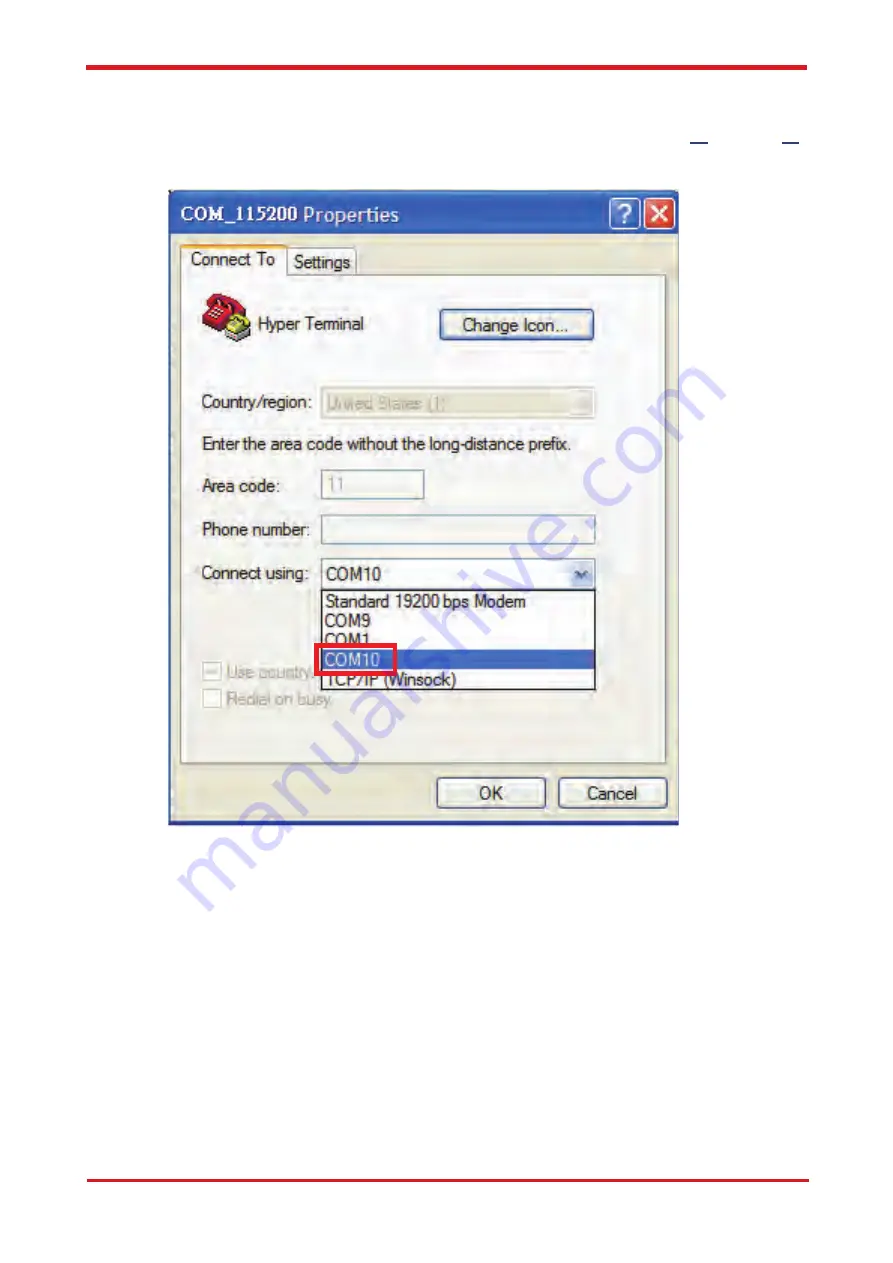
6.   In the connection that you have just set up, click 

File

 | 

Properties

. Select 

[Connect   


To]

 tab

.

 From 

[Connect using]

 drop down list, select the correct com port by checking  


it up at Windows XP's 

[DeviceManager] 

as previously mentioned on page 

16

 and page 

20

.  


Go there by clicking 

Start

 | 

Control Panel

 | 

System

 | 

Hardware

 | 

Device Manager.


S&T 

Confidential 

Documents

Содержание CAREU U1

Страница 1: ...CAREU U1 Vehicle Tracker User Guide SYSTEMS TECHNOLOGY CORP Version 1 01 Reference No AVL CU U1 00 1111UEN Date June 23 2011 S T C o n f i d e n t i a l D o c u m e n t s...

Страница 2: ...document is subject to change without notice at any time Disclaimer The information specification images and photos in this user guide are subject to change without notice and without obligation to no...

Страница 3: ...Rear View 6 Chapter 3 Getting Started with CAREU U1 7 3 1 Hardware Installation 7 3 2 Connector Pin Assignment 12 3 3 USB Device Driver Installation 14 3 4 Device Configuration 21 3 5 Communication Se...

Страница 4: ...helps back end users proceed with the analysis and the applications of vehicle transport management anti theft security and tracking 1 1 Features Multiple serial ports and easy installation Voices SM...

Страница 5: ...locks un locks starter interrupt ignition battery engine and panic button The firmware in the device applies intelligent filtering to overcome coverage limitations for both GPS and GSM GPRS networks...

Страница 6: ...ts to any customer monitoring points by door switch anti thief or actuators The A D input that connects the analog signal sensor to the AVL such as the fuel or temperature sensor With the built in RF...

Страница 7: ...CAREU U1 Vehicle Tracker User Guide Chapter 1 4 1 5 Related Document 1 CAREU U1 Protocol Document S T C o n f i d e n t i a l D o c u m e n t s...

Страница 8: ...cker User Guide Chapter 2 Taking A Tour of CAREU U1 This chapter will guide you to the major connectors of the U1 device 2 1 Dimensions Dimensions 108mm x 72mm x 31mm 72 00 31 10 108 00 S T C o n f i...

Страница 9: ...Car Battery I O Input Output Connector including basic I O RS232 SERIAL Serial Connector GSM SMA Connector for GSM External Receiver RF RF Connector for RF Receiver GPS SMA Connector for GPS External...

Страница 10: ...ion 1 SIM Card Installation Remove the screw at the bottom of the device to open it Then you will find the SIM card slot inside Insert your SIM card into the device with SIM card s gold area down and...

Страница 11: ...s recommended that a matching torque 7 10 inch pounds 80 110 N cm should be used for the SMA connector 3 GSM Antenna Connection Connect the GSM antenna to the SMA connector jack on the front side of t...

Страница 12: ...nnect 4 wire power cable to the power connector on the front side of U1 device 8 30V Connect the 8 wire cable to U1 device which enables U1 s connection to your system and also to related peripherals...

Страница 13: ...e Connection 7 G Sensor Installation Consideration The device uses a 3 axis G Force sensor to detect the vehicle motion and the impact on the vehicle The X Y and Z axis definition will be affected by...

Страница 14: ...wire cable completely into to the seial port on the front side of the device See the illustration below 9 Speaker Installation Optional Connect the speaker set to the 8 wire cables first Plug the con...

Страница 15: ...Description I O Electrical Characteristic 1 Analog Input 2 Analog Input 2 I DC VIN 30V 0V default Input 3 Optional Positive Trigger input 3 I DC VIN 30V 0 7V High Active 2 Input 4 Positive Trigger in...

Страница 16: ...tput O Vo 5V Vout 1 3 Total Imax 500mA 2 GND Signal ground 3 TX1 RS232 Data output O 4 RX1 RS232 Data input I 5 Vout 2 Supply voltage output O 6 GND Signal ground 7 TX2 RS232 Data output O 8 RX2 RS232...

Страница 17: ...to manually install the USB driver for the U1 device In the following content of this section you will be guided to how the installation can be done in both cases To install the device driver for U1 C...

Страница 18: ...ion If the wizard prompts to help you install the software for STMicroelectronics Virtual COM Port Select Install the software automatically Recommended Press Next button to proceed The wizard proceed...

Страница 19: ...Tracker User Guide The installation completes In Device Manager U1 device is included under Ports COM LPT as STMicroelectronics Virtual COM Port COM port number is displayed as well S T C o n f i d e...

Страница 20: ...er you select No not this time if the wizard only prompts to help you install software for USB device you need to manually install the driver Select Install from a list or specific location Advanced P...

Страница 21: ...se locations Check Include this location in the search Press Browse button to assign where your U1 device driver locates on your local disk U1 s USB device driver is free for download on S T s website...

Страница 22: ...Chapter 3 19 CAREU U1 Vehicle Tracker User Guide Press Next button to proceed The wizard proceeds to install the driver S T C o n f i d e n t i a l D o c u m e n t s...

Страница 23: ...U U1 Vehicle Tracker User Guide The installation completes In Device Manager U1 device is included under Ports COM LPT as S T Tracker COM port number is displayed as well S T C o n f i d e n t i a l D...

Страница 24: ...formation of your location complete them to proceed 3 On the File menu of HyperTerminal click New Connection 4 In the Name box type a name that describes the connection In Icon box click an appropriat...

Страница 25: ...roperties Select Connect To tab From Connect using drop down list select the correct com port by checking it up at Windows XP s DeviceManager as previously mentioned on page 16 and page 20 Go there by...

Страница 26: ...de 7 In File menu click Properties Click Settings tab Press ASCII Setup button 8 In ASCII Sending group box Select both Send line ends with line feeds and Echo typed characters locally Press OK button...

Страница 27: ...e displayed 10 In HyperTerminal window type in the command AT VERSION and press Enter key The hardware and firmware version will show As long as your HyperTerminal window appears as the screenshot bel...

Страница 28: ...DST command to set a SMS control center phone number or short code For example if the SMS control center phone number is 886123456789 the AT SMSDST command to be issued into HyperTerminal should be AT...

Страница 29: ...ername username Password password OK AT HOSTS 1 0 60 148 19 10 6000 Server IP address 60 148 19 10 and Port number 6000 OK AT RETRY 5 10 Message retry settings OK AT IPTYPE 1 Using TCP IP mode OK AT G...

Страница 30: ...ction The setting of GPS tracking can be done by using AT PDSR command For example AT PDSR 1 30 0 0 2 0 0 1 1 Tracking through GPRS by time interval 30 seconds OK For simple testing GPRS run the TCP S...

Страница 31: ...s now available for your download at ftp ftp systech com tw AVL AVLS_TracerPlus Please contact your account manager with S T to request a set of user name and password to access the FTP You can also a...

Страница 32: ...Chapter 3 29 CAREU U1 Vehicle Tracker User Guide The main page of Intelli Fleetweb appears as below S T C o n f i d e n t i a l D o c u m e n t s...

Страница 33: ...ade the firmware follow the procedure below 1 Connect the device to your PC with the USB cable 2 Connect the device to power 3 Power on the device 4 Run ServerUSeries exe A window displays as follows...

Страница 34: ...RS Coding Scheme CS1 CS2 CS3 and CS4 GSM Antenna External SIM Interface SIM card 1 8V 2 9V supported GPS Functionality Receiver 50 Channels Sensitivity Tracking 160dBm Antenna Type External GPS Active...

Страница 35: ...configurable 19200bps Serial 3 configurable 19200bps Input Ports Positive Triggers 2 Negative Triggers 2 Analog Inputs 2 0 30V 12 Bits Output Ports Negative Triggers 3 Total 500mA Electrical Power So...

Страница 36: ...igital Map and Car Navigation Systems If you need information about other vehicle tracking solutions or products please contact us by the phone and fax numbers listed below or visit our websites Conta...

Страница 37: ...the user is encouraged to try to correct the interference by one or more of the following measures Reorient or relocate the receiving antenna Increase the separation between the equipment and receive...

Отзывы: