Installation & Operation Manual Merlin GDPX+
GDPXPLUS - IOM Iss: 8 02-21
8
Wiring your Detector
12-24VDC power and Modbus communication data cables are wired to Merlin gas detection panels –
GDP2X or GDPX+. Both terminals are identified as [DETECTOR CHAIN + - D+ D-]. Up to 16 detectors can
be connected, chained in parallel up to approx. 100 metres from the panel depending on chain
configuration, wire type for power and condition.
If devices are not grounded, they can give false readings or become a safety hazard!
Where connections may exceed 100 metres from one control panel – Contact your supplier!
Ensure the termination resistance switch is turned on at each end of a chain!
MODBUS
Connection
A shielded and twisted 2 or 4 core cable is used to wire the data terminals [D+ & D-).
Any cable with similar characteristics can be used to connect all the devices together.
The shielding can be of 2 types: braided [mesh of thin conducting wires] or foil
(consisting of a thin sheet of metal covering the twisted wires).
One example of such cable is BELDEN 3082A. If you are encountering noise or
irregular problems with a bus link, the problem is likely related to grounding,
incorrect shielding or wiring mains power next to Modbus wiring.
To ground the data cable, the shield should be connected to ‘Power’ [-] terminals!
Creating a Detector Chain
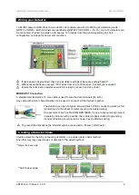
Create a detector chain by connecting detectors in a parallel (daisy chain) method.
Any other way may cause issues or damage to the overall system.
**Single chain example
.
**Split chain example


