

Merlin 1000V
Product Data Sheet
S&S Northern Ltd
4
2.8
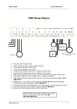
CO2/Gas Detected.
The terminals detailed on the circuit board as “Gas Detector”. These
connections
are “+,-“ and ”
” these can be wired to a Merlin Natural gas, Carbon monoxide
or LPG detector. This terminal can also be wired to a CO2 monitor to shut off the system in the
event of High CO2 levels. If no detector is being used leave the link in between
the “
”.
2.9
FS 123.
This terminal switches 12v when the key is turned on and off. This can be linked to a
fan switch (panel supplied separately) which can provide power to the fans when the control
panel is switched on.
2.10
Fan PD Switch.
This terminal is used to receive an input signal from external air pressure
switches or external current monitors. This terminal is linked out as factory setting. Wiring to
the air pd switches & current monitors should be made using a two-core cable and volt free
connections.
2.11
12v DC.
This is a permanent 12v DC output when there is power at the panel.
2.12
Internal Buzzer.
Operates at 65dB measured 30cm from closed panel.
Note: all low voltage connections should be made using a screened cable to
avoid electrical interference should not be in the same conduit as per the low
voltage directive.
3
Operation Instructions
3.1
How to turn the system on and off
1. Turn off all open appliances.
2. Turn the key switch to on position.
3. To turn the system off, turn the key switch to off position.
3.2
Explanation of LED status
Power LED
When the system is connected to the mains supply, the Red LED of the S&S Logo
located in the bottom right corner of the panel will illuminate. When no power is
present, this LED will not light up.
RED = OK
OFF = No power to 1000V
Gas on LED
When the gas service touch button has been activated the Merlin 1000V will check the
installation for gas leaks. If gas proving is successful, the gas valve will open and the
green ‘Gas On’ LED will illuminate.
GREEN = Gas On
OFF = Gas Off
Testing LED
This LED will illuminate GREEN for approximately 30 seconds when the panel is
checking the integrity of the gas installation upon start up.
GREEN = proving the gas line, do NOT operate any appliances.
Test Fail LED
Under normal working conditions this LED is off. When the panel detects a gas leak
on start-up or incorrect wiring at the gas pressure transmitter the LED will illuminate
AMBER and the gas valve will remain closed.
OFF = OK
AMBER = gas proving failed


