7.2.9 Power Maintenance Page
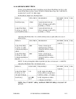
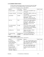
The Diagnostics 1 page (see Figure 7-2) consists of readouts that monitor the
unit’s internal environment and the unit’s power measurements for reference.
Any of these items that are outside normal operating limits will post an on-screen
error by way of the systems built-in-test processes.
Figure 7-2: Internal Diagnostics 1
Note: On ST3400 with Mod-A, the following differences should be noted:
•
The power supply monitor list is slightly different than shown above;
•
Any power supply out-of-tolerance will change from green to red.
•
If inverter inputs are floating they will read 1.3V not 0.0V. When
grounded they will read 0.0 V
82002-IM-L
ST3400 INSTALLATION MANUAL
7-19
Содержание ST3400
Страница 24: ...THIS PAGE INTENTIONALLY LEFT BLANK ST3400 INSTALLATION MANUAL 82002 IM L 2 6 ...
Страница 44: ...THIS PAGE INTENTIONALLY LEFT BLANK 5 2 ST3400 INSTALLATION MANUAL 82002 IM L ...
Страница 75: ...THIS PAGE INTENTIONALLY LEFT BLANK 82002 IM L ST3400 INSTALLATION MANUAL 7 31 ...
Страница 76: ......
Страница 78: ...THIS PAGE INTENTIONALLY LEFT BLANK 8 2 ST3400 INSTALLATION MANUAL 82002 IM L ...
Страница 80: ...THIS PAGE INTENTIONALLY LEFT BLANK 9 2 ST3400 INSTALLATION MANUAL 82002 IM L ...
Страница 86: ...THIS PAGE INTENTIONALLY LEFT BLANK 11 2 ST3400 INSTALLATION MANUAL 82002 IM L ...
Страница 88: ...12 2 STC Cessna 421C Series 12 2 ST3400 INSTALLATION MANUAL 82002 IM L ...
Страница 89: ...12 3 STC King Air C90 200 300 and B300 Series 82002 IM L ST3400 INSTALLATION MANUAL 12 3 ...
Страница 91: ......
Страница 92: ......


