S&C Vista SD Скачать руководство пользователя страница 26

26

    S&C Instruction Sheet 695-510

Appendix A

S&C Vista SD Underground Distribution Switchgear 

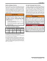
was designed to allow dc testing of the cables with the 
other ways of the gear energized. After testing, the dc test  
equipment should be used to discharge any stored charge on 
the cable. The dc test voltages and dc cable thumping voltages 
should not exceed the voltages given in Table 2.


WARNING

When testing cables connected to energized switchgear, 
proper isolation of the power-frequency source from the 
dc test source must be maintained . Follow the recom-
mendations provided by the manufacturer of the dc test 
equipment or fault-locating equipment . Follow the user’s 
operating and safety procedures for grounding the cable, 
connecting the dc test source, isolating the dc test source 
(in case of flashover), ungrounding the cable, applying the 
dc test source, discharging the cable, and regrounding the 
cable .

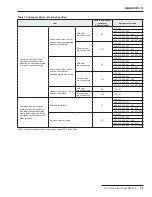
Table 2. Maximum Cable-Testing and Cable-Thumping 

Dc Withstand Voltages

Vista SD Switchgear Rating, kV

Dc Cable-

Test 

Voltage, kV

Dc Cable- 

Thumping  

Voltage, 

kV

IEC

IEEE

Impulse 

(BIL)

12

17 .5

95

34

17

24

29

125

40

20

 The dc cable-thumping voltage is 50% of the dc cable test voltage 

because voltage doubling will occur at the open end of the cable, which 
is assumed to be a unit of Vista SD Underground Distribution Switchgear . 
If the open end of the cable is grounded, the dc cable-thumping voltage 
applied to the cable and switchgear can be increased to the dc cable-test 
voltage .

Very Low Frequency (VLF) Cable Testing

IEEE Standard 400.2, “IEEE Guide for Field Testing of Shielded 
Power Cable Systems Using Very Low Frequency (VLF) (less 
than 1 Hz),” addresses the application of 0.01- to 1-Hz high-
voltage ac excitation as one means for evaluating a shielded 
power cable system during an acceptance test or a maintenance 
test. The cable system must be taken out of service for this 
testing.

An acceptance test is a field test made after installation of 

the power cable system, including terminations and joints, 
but before the cable system is placed in normal service. A 
maintenance test is a field test made during the operating life 
of a power cable system to detect deterioration and to check 
serviceability of the system.

VLF cable testing may subject the S&C Vista SD Under-

ground Distribution Switchgear to the ac test voltage when 
the cables are attached to the switchgear. S&C recommends 
that the Vista SD Underground Distribution Switchgear be 
completely de-energized and disconnected from all power 
sources when performing VLF cable testing. However, Vista 
SD switchgear has been designed to allow VLF testing of the 
cables with the other ways of the gear energized, if necessary. 

Upon completion of the VLF cable testing or an interrup-

tion in the testing, the test set must be turned off to discharge 
the cable circuit and test set. The cable system must then be 
grounded.

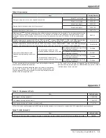
The VLF sinusoidal waveform test voltage applied to the 

S&C Vista SD Underground Distribution Switchgear must not 
exceed the voltages listed in Table 3 on page 27.

Содержание Vista SD

Страница 1: ...Style 11 Pad Mounted Style 12 Closing the Doors and the Hinged Roof 14 Resetting Visi Gap Fault Interrupters All Styles 15 Locking in Open or Closed Position 17 Checking for Voltage Using the Optional...

Страница 2: ...tallation and operation of S C Vista SD Underground Distribution Switchgear are included in the Installation and Operation Information Kit provided with each switchgear assembly A catalog dimensional...

Страница 3: ...rise to the immediate purchaser s or end user s claim All other warranties whether express or implied or arising by operation of law course of dealing usage of trade or otherwise are excluded The onl...

Страница 4: ...recommended precautions are not followed NOTICE NOTICE identifies important procedures or requirements that can result in product or property damage if instructions are not followed Following Safety I...

Страница 5: ...ents Live G 6700 C WARNING Do Not Block Pressure Relief Device not visible G 6742 D WARNING Before Using Voltage Tester Always Test for Proper Operation G 9451 Figure 1 Location of Safety Labels Model...

Страница 6: ...C WARNING Do Not Block Pressure Relief Device not visible G 6742 D WARNING Before Using Voltage Tester Always Test for Proper Operation G 9451 Figure 2 Location of Safety Labels Model 321 3 way vault...

Страница 7: ...e Using Voltage Tester Always Test for Proper Operation G 9451 E WARNING Keep Out Hazardous Voltage Inside G 6398 Figure 3 Location of Safety Labels Model 321 3 way pad mounted style unit shown E E WA...

Страница 8: ...oor The use of undue force may damage the door latching mechanism 7 Safety Labels Do not remove or obscure any of the DANGER WARNING CAUTION or NOTICE labels 8 Energized Bushings Always assume the bus...

Страница 9: ...y using a piece of rope attached to the manual handle or by a user furnished universal pole of the appropriate length equipped with a standard fitting Opening and closing speed of the vacuum interrupt...

Страница 10: ...otential indication feature optional 600 A bushing adapters are field replaceable Ground bus optional Parking stands optional Operating mechanism CT Figure 5 S C Vista SD switchgear has the features a...

Страница 11: ...To open the load interrupter switch or fault interrupter rotate handle counterclockwise b To close the load interrupter switch or fault interrupter rotate handle clockwise The manual operating handle...

Страница 12: ...could result in personal injury STEP 4 To gain access to the termination compartment lift the latch handle to open the right side door or the center door See Figure 12 a Open the door far enough to p...

Страница 13: ...ter rotate the handle clockwise The manual operating handle may be operated from a variety of locations using a rope a shotgun stick or by hand illustrated a b Figure14 Rotatetheoperatinghandleguideri...

Страница 14: ...hinged roof to sag against the hold open mechanism At the other end of the enclosure push up on the hinged roof just enough to allow that hold open mechanismlatchtobereleased Lower the hinged roof int...

Страница 15: ...and without hesitation all the way to the stops to reset the fault interrupter See Figure 22 a b Figure 22 Resetting the fault interrupter after a fault a vault mounted style b pad mounted style STEP...

Страница 16: ...r a vault mounted style b pad mounted style STEP 8 Check the POSITION indicators to confirm the fault interrupter is closed See Figure 26 Figure 26 The POSITION indicator after the fault interrupter h...

Страница 17: ...b Locked closed Figure 28 The loadinterrupter switches or fault interrupters may be padlocked in either position To prevent operation of a load interrupter switch or fault inter rupter insert a padlo...

Страница 18: ...f the operating mechanism front panel around the Potential Indication feature Petro leum based solvents should not be used on or around Vista SD Underground Distribution Switchgear STEP 2 Unscrew the...

Страница 19: ...e phased as follows a Set the voltmeter for volts ac b Connect one of the test probes of the voltmeter to the Neutral Jack of the way to be phased c Placetheothertestprobeoneachofthetestjacks in turn...

Страница 20: ...ng different phases of the two ways the voltage should be 1 7 to 2 times the phase to neutral voltage measured in Step 3 See Figure 32 b d Keep the test probe on Test Jack 1 of the first way and move...

Страница 21: ...ters from all power sources including backfeed test for volt age and properly ground 4 Always assume the bushings are energized unless proved otherwise by test or by visual evidence of an Open Circuit...

Страница 22: ...olive green finish 9991363 493 for seafoam green 9991363 488 for equipment green and 9999 061 for red oxide primer See Figure 34 No other finish or primer is approved The area to be touched up should...

Страница 23: ...ut opening the latch The following procedure describes how to open the switchgear enclosure and replace the shear pin Tools Required Needle nose pliers Slotted flathead screwdriver Parts Required Shea...

Страница 24: ...360 STEP 9 Close and secure the hinged roof per the instruc tions in Closing the Doors and the Hinged Roof on Page 14 Closing and Securing the Enclosure if Replacement Shear Pin is Unavailable If the...

Страница 25: ...c withstand tests The presence of these values does not imply a dc withstand rating or performance requirements for the switchgear A dc withstand design test is specified for new equipment because the...

Страница 26: ...switchgear can be increased to the dc cable test voltage Very Low Frequency VLF Cable Testing IEEE Standard 400 2 IEEE Guide for Field Testing of Shielded Power Cable Systems Using Very Low Frequency...

Страница 27: ...ned Follow the recom mendations provided by the manufacturer of the VLF test equipment Follow the user s operating and safety proce dures for grounding the cable connecting the VLF test source isolati...

Страница 28: ...nterrupt rated current Table 5 Vista Gap Load Interrupter Switch Ratings Applicable Standard Freq Hertz Visi Gap Load Interrupter Switches Voltage kV Amperes Nom Max BIL Continuous Load Dropping and L...

Страница 29: ...on top Mild steel mounting stand V2 110 101 303 312 321 330 404 413 422 431 440 505 514 523 532 541 550 606 615 624 633 642 651 660 Stainless steel mounting stand V12 110 101 303 312 321 330 404 413 4...

Страница 30: ...541 550 606 615 624 633 642 651 660 Stainless steel 6 inches K17 210 201 303 312 321 330 404 413 422 431 440 505 514 523 532 541 550 606 615 624 633 642 651 660 12 inches K18 210 201 303 312 321 330 4...

Страница 31: ...ntinuous ground bus Connects to all load interrupter switches and fault interrupters provides a convenient location to attach cable concentric neutrals separable connector drain wires and user provide...

Страница 32: ...rip signal from a remote location or an external relay Requires a user furnished 220 240 Vac 50 60 Hz control power source In addition to standard overcurrent control for all fault interrupters R33 10...

Страница 33: ...control For connecting a control to a user furnished personal computer in the field For personal computers having a 25 pin serial communication port TA 2366 For personal computers having a 9 pin seria...

Страница 34: ...S C equipment green outdoor finish 9991363 488 S C red oxide primer 9999 061 Table 13 Auxiliary Contacts Receptacle Connector Pin Function A n c B Vacuum interrupter closed NO C Vacuum interrupter cl...

Страница 35: ......

Страница 36: ......

Страница 37: ......

Отзывы: