S&C PMH Скачать руководство пользователя страница 19

S&C ELECTRIC COMPANY 


s

INSTRUCTION SHEET

 663-503

Page 19 of 35

August 14, 1995

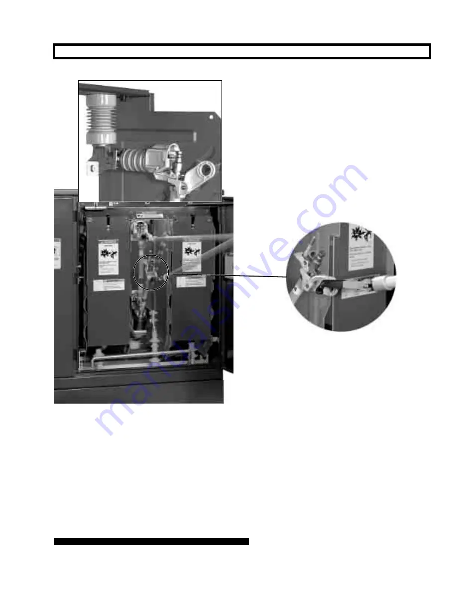
SWITCHING WITH UNI-RUPTER — Continued

Figure 18. Closing the fuse. Inset on right shows close-up of Grappler in position to close the fuse.
Top inset shows close-up of Uni-Rupter with the fuse fully closed.

Содержание PMH

Страница 1: ...Removing the Fuse 20 INSTRUCTIONS For Operation Section Page Number RE FUSING How to Detect and Replace a Blown Fuse 23 Installing the Fuse in the Mounting 24 FINAL CHECKS BEFORE WALKING AWAY 25 IF OP...

Страница 2: ...or the equipment Ratings for this gear are listed on a ratings label on the interior of the doors right hand doors only for double door models Transfer Control For instructions regarding field pro gra...

Страница 3: ...out this instruction sheet as well as on labels affixed to the S C Source Transfer PMH Pad Mounted Gear Familiarize yourself with these types of messages and the importance of the various signal words...

Страница 4: ...ED TERMINALS Always assume that both sets of power terminals on any Mini Rupter Switch or fuse are energized unless proved other wise by test by visual evidence of open circuit con ditions on both set...

Страница 5: ...ng performed v Fuse Side These barriers are intended for tempo rary use to isolate the fuse from the contacts of Uni Rupter while work is being performed 19 CLOSING FUSES Closing a fuse into a faulted...

Страница 6: ...ith the various compo nents and locations Figure 1 Low voltage control compartment Bolted cover provides access to input plug and shorting receptacle for Micro AT control Operator target indicates whe...

Страница 7: ...Test keys for simulating overcurrent and loss of voltage on right source Right source voltage indicating lamp Manual automatic operation selector switch When in MANUAL prevents an automatic source tra...

Страница 8: ...e of S C Micro AT Source Transfer Control Remote indication wiring provided with optional remote indication feature Catalog Number Suffix Y4 leads to a terminal block for user s connections Supervisor...

Страница 9: ...Viewing window for visible verifica tion of switch position is removable for phasing To remove window loosen wing head screws and lift window off alignment bolts Current sensors furnished for attach m...

Страница 10: ...dow is provided in the switch compartment to allow positive visual verification of switch blade posi tion see Figure 4 The operator target see Figure 1 signals OPERATOR CHARGED to indicate that the op...

Страница 11: ...ges when voltage is present on the associated source The charging operation takes approximately 25 seconds If Control Power Is Lost and Operator Is Charged To manually operate the stored energy operat...

Страница 12: ...ing the front barriers refer to the DANGER on pages 4 and 5 and the WARNING on page 10 Place the dual purpose front barrier in the slide in position whenever the Mini Rupter Switch is open When the ba...

Страница 13: ...rator will stall in a par tially closed position To correct this condition follow the directions under IF OPERATOR STALLS on page 26 To restore the dual purpose front barrier to the normal suspended p...

Страница 14: ...oor Distribution 14 4 kv and 25 kv S C ELECTRIC COMPANY s 663 503 INSTRUCTION SHEET Page 14 of 35 August 14 1995 MINI RUPTER SWITCHES Continued Figure 11 Alternate method of replacing front barrier us...

Страница 15: ...urrent limiting fuse holders refer to S C Instruction Sheet 660 500 WARNING When selecting current limiting fuses the voltage rating of the fuses must conform to the recommendations in Appendix E Fail...

Страница 16: ...nto which the fuse is to be installed See Figure 13 Insert the barrier into the slide in position using the Grappler as illustrated in Figure 14 Note that the barrier is supported on the Grappler pron...

Страница 17: ...g the contacts will close the circuit which can cause a flashover and serious injury Always place the dual purpose front barrier in the slide in position whenever a fuse is open or is being removed fr...

Страница 18: ...o carry and interrupt rated current 6 With the Grappler prongs pointed downward insert the longer prong into the pull ring of the fuse See inset of Figure 18 Then with one s face turned away close the...

Страница 19: ...T 663 503 Page 19 of 35 August 14 1995 SWITCHING WITH UNI RUPTER Continued Figure 18 Closing the fuse Inset on right shows close up of Grappler in position to close the fuse Top inset shows close up o...

Страница 20: ...positioned for opening stroke with longer prong inserted in the fuse pull ring WARNING A Note on Single Pole Switching In single pole switching of ungrounded primary three phase transformers or banks...

Страница 21: ...ous injury or death 6 Place the dual purpose front barrier associated with the fuse to be removed in the slide in position Use the Grappler for this as illustrated in Figure 21 Note that the barrier i...

Страница 22: ...ing the fuse from its hinge Touching the contacts will close the circuit which can cause a flashover and serious injury Always place the dual purpose front barrier in the slide in position whenever a...

Страница 23: ...The blown fuse target retracts within the end fitting or holder when the blown fuse unit or interrupting module is replaced SML 4Z Power Fuse A fluorescent orange target in the translucent SML 4Z Hol...

Страница 24: ...t current should also be replaced For instructions on replacing current limiting fuses in S C Holders refer to S C Instruction Sheet 660 500 S C Holders will accommodate the current limiting fuses lis...

Страница 25: ...p is not lighted NOTE A lighted READY lamp indicates that the status of associated components is normal but an absence of illumination does not necessarily mean that the control is inoperative For exa...

Страница 26: ...on See Figure 25 Restore the stored energy operator to a normal latched open condition after such an occurrence as follows 1 Make sure that the manual automatic operation selector switch is in MANUAL...

Страница 27: ...serious injury or death 1 Access to pad mounted gear must be restricted only to qualified persons See Qualified Persons on page 2 2 Always follow safe operating procedures and rules 3 Before touching...

Страница 28: ...ali fied persons Enclosure Finish The responsibility for ensuring that a finish protects the enclosure lies with both the manufacturer and the user S C Source Transfer PMH Pad Mounted Gear is finished...

Страница 29: ...ast two min utes after the stored energy operators are charged before initiating a transfer operation APPENDIX A Dielectric Testing When high voltage dielectric tests are to be performed on S C Source...

Страница 30: ...ities shown for S C Power Fuses with Uni Rupter represent the fault closing capabilities of the fuse with Uni Rupter when the fuse is closed with a purposeful thrust without hesitation Following the s...

Страница 31: ...luded see ACCESSORIES on page 33 C11 Mounting Provisions for a Fault Indicator in each switch compartment Note Accommodates three phase indicator with single phase sensors Without viewing window in do...

Страница 32: ...specified cable termination options suffixes U2 and U3 cannot be accommodated In addition when optional features M1 and M2 are both specified only one cable guide is provided at each switch terminal...

Страница 33: ...T control communications card see optional feature Y8 on page 32 to user furnished personal computer For personal computers having 25 pin serial communication port TA 2320 For personal computers havin...

Страница 34: ...5 15 5 6 30 40 100 6 30 40 50 65 100 3142 A3 3142 A1 3142 A2 3142 A1 3142 Cooper Power Systems McGraw Edison NX 8 3 8 3 15 5 15 5 1 5C 40C 50C 100C 1 5C 40C 1 5C 100C 3142 A3 3142 A1 3142 A2 3142 RTE...

Страница 35: ...gs appropriate for system line to ground voltage i e fuses with a voltage rating lower than line to line voltage but greater than or equal to maxi mum system line to ground voltage S C can only recom...

Отзывы: