background image


32 


3. Indication of course-up (C-UP) 

Menu 

 View 

 Mode 

 Input 

 Course 

 Input 

 Esc 

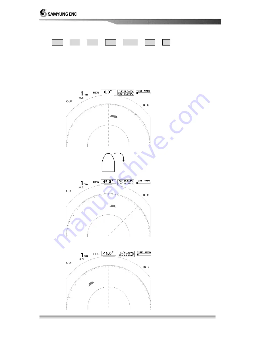
 Make the ship’s head line on the screen when the course-up is excuted. 


 Even though ship’s head direction is changed, Echo image bearing moves as   

much as the variation of ship’s heading bearing. 

 When you change the track widely, set the course up again from the MENU. 

 It requires the equipment like GYRO COMPASS to obtain bearing information. 


    Head Line moves to the right. 


    When the course up is reset 

When  the  own  ship  turn  right 

to 45 degree   

Содержание SMR-3700

Страница 1: ...t Function 10 2 1 2 Directional Key 11 2 1 3 Display Characters 11 2 2 Display Description 12 2 3 Menu Functions 13 2 3 1 Menu Composition 13 2 3 2 MENU Functions 16 Chapter 3 How to operate the unit...

Страница 2: ...ge the way of displaying bearing ine cursor 33 3 3 18 To compensate the magnetic 33 3 3 19 To measure the time to the target 34 3 3 2 0 T o d i s p l a y t h e W a y p o i n t 3 4 3 3 21 T o d ispla y...

Страница 3: ...ADJ 47 5 6 7 MT RPM ADJ 47 5 6 8 Upgrading software 47 5 6 9 Setting 47 5 6 10 Factory defult set 47 Chapter 6 Maintenance 6 1 General Maintenance 48 6 1 1 Cleaning 48 6 1 2 Chect out the tightness o...

Страница 4: ...ut 4KW Max Range 36NM Display Unit SMR 3600 monitor is designed to receive the input signal from Scanner and displays the optimum conditions on the TFT LCD screen based on the SAMYUNG s best digital s...

Страница 5: ...ion Q y Samyung CODE Remark Manual 1 SMR 3700 ME SCANNER DISPLAY CABLE 1 RSU 3700 15M 15m POWER CABLE 1 ACC CAB 010 3m SURGE CABLE 1 STR 595 3m 1 4 Construction 150 4 M10 1 5 0 20 600 274 Pic 1 1 RSU...

Страница 6: ...6 140 138 138 SCANNER 265 133 133 258 POWER DOWNLOAD NMEA FUSE 7A EARTH AIS EXTENSION 67 322 303 307 293 25 4 M6 194 Pic 1 2 SMR 3700 External diagram of Display...

Страница 7: ...ing Environmental Condition 1 Temperature Scanner 25 55 Display 15 55 2 Relative Humidity Scanner below 95 on 35 Display below 95 on 35 3 Relative Wind Speed 51 5m sec 100knots Power Consumption 60W D...

Страница 8: ...ay Screen 10 4 Color TFT LCD Scale Zoom In Less than the bigger one 1 of used range or 70m VRM 000 36 0 NM 000 64 0 NM Digital EBL 000 359 Digital Display Sync Type Manual Automatic Switchable Bearing...

Страница 9: ...Switch 16 Menu Switch 17 Cursor Switch 18 ESC Switch 19 Enter Switch 20 Direction Button 8 Directions Switch 21 Brightness Switch 23 Power Switch 24 Transmission Switch Menu Type POP UP Type 1 5 4 Con...

Страница 10: ...pe to the previous screen or menu display To indicate the cursor on the screen To control the target memory function To indicate the heading line the parallel line To set up the monitor zone and alarm...

Страница 11: ...operate the exclusive keys 2 1 3 Display Description Description Position Display Characters ALARM Right Top ALM1 ALM2 Interferance Right Top IR0 IR1 IR2 Sector Blank Right Top BLANK Auto Tunning Righ...

Страница 12: ...VRM 2 VRM F VRM Gain control display Snow Rain clearing control display Sea clutter control display Cursor Position Parallel Line F EBL Guard Zone 1 1 VRM 2 VRM Alarm 2 Zone 2 EBL 1 EBL Heading Line B...

Страница 13: ...ct any wishful setup menu by using direction button There are total of five 5 different menus and each menu function explained as following Echo Menu Menu setting for the target display AIS Menu Menu...

Страница 14: ...14 Display Menu Communication Menu System Menu Initial Display...

Страница 15: ...te by press TRAIL Revoluation can be adjusted from Off status then 1st to 4th revoulouation Current setting status will be disply on the left upper screen cornor Target boost Set and adjust the target...

Страница 16: ...AIS or not Colors Selecting a color of AIS target you can choose Green Red Blue White or Black CPA TCPA AIS Alarm Setting Setting menu for the AIS target wreck alarm of CPA distance set TCPA is setti...

Страница 17: ...vailable to select N UP C Up and True Motion mode when thereis an external signal of bow Course means the waypoint set externaly Colour It s available to select the colours between white green red for...

Страница 18: ...rsor Cursor Float Zoom up the the cursor is Sector Blank You can set Sector Blank in the radius 360 by 1 degree It will be displayed with blue broken lines Compass You can turn on off the compass func...

Страница 19: ...the transmission speed and communication status It provides Communication speed at 4800 9600 and 38400 You can check the communication status of receiving signal from other equipment AIS A function to...

Страница 20: ...ding Self adjustment is to adjust information of self heading Tuning You can set Auto Manual a way of setting TX and RX Installation Setting A function to set a equipment please refer 5 6 article It s...

Страница 21: ...s Press button again to convert the TX status to the stand by status 3 1 2 Tuning control It is required to control the tuning of the unit both manually and automatically The conversion is selectable...

Страница 22: ...for processing 3 2 1 Brightness change Press brightness key Push key to brighten the screen push key to darken the screen There are 10 levels you can adjust 3 2 2 Language Selection Menu System Langua...

Страница 23: ...TO in the centre of bottom of the screen it will be displayed GAIN A in the right corner of the bottom of the screen This function is set the optimum environment without adjusting gain but there isa p...

Страница 24: ...ill be displayed AUTO in Rain CL in the middle of bottom of screen it ll be displayed RAIN A in the right conner of bottom of screen This function is to make a best display setting without managing th...

Страница 25: ...witch on Sea Clutter remove it will be displayed AUTO in the Centre of bottom of screen it will displayed SEA A in the right corner of bottom of the screen This function is automatically set the optim...

Страница 26: ...me out of the zone In each case the alert sound will come outt Select Ring or Fan Ring function will create ring shaped guide zone and Fan function will create Fan shaped guide zone Press Adjust and t...

Страница 27: ...ting to own ship s Radar air line 1 Press the interference removal key Whenever pressing button it marks with IR 1 IR 2 IR 3 in order in the top right screen IR 1 Before Interference Removal After Int...

Страница 28: ...own ship moves to the position of the cursor by pressing centrer movement It can be moved up to 60 percent of the screen 3 Once center movement key is pressed it will turn back to the original positi...

Страница 29: ...he screen To exit press the esc key Ref F EBL VRM can be used to indicate EBL VRM on the specified position 4 Measurement of the distance and bearing by using Cursor By using Cursor cross shaped curso...

Страница 30: ...ut Esc Ship s head is displayed to the HEAD UP If ship s head is changed ECHO image bearing on the screen is also changed If you could not obtain bearing reference from external navigation equipment l...

Страница 31: ...irection of the North the line to 10 degree indicates the ship s heading line The angle of bearing will be changed based on the North direction on the screen It requires the equipment like GYRO COMPAS...

Страница 32: ...ship s head direction is changed Echo image bearing moves as much as the variation of ship s heading bearing When you change the track widely set the course up again from the MENU It requires the equ...

Страница 33: ...e own ship and True North as a base 1 Relative Indication Menu View EBL Cursor Input Relative Input Esc Make the cursor and the bearing value of EBL indicate based on ship s heading line Ship s head l...

Страница 34: ...upper left side of the screen the status W1 W4 will be displayed 2 Deactivation of the target trace Menu Echo Target Trace Input OFF Input Esc or TRAIL 3 3 20 To display ECHO image wider on the radar...

Страница 35: ...k and set the LCD brightness to the low level it will help relieving eye s fatigue 3 4 Connection to the external navigation equipment At the rear side of the indicator connect to the external navigat...

Страница 36: ...5 6 7 4 AIS SCN 16 8R NMEA GND 2 1 SMR 3700 If Compass is not installed in vessel 38400 6 RX TX NMEA0183_RS 422 GND TX RX 7 SCN 16 7R 3 GND TXD NMEA0183_RS 232 AIS UNIT GND COMPASS UNIT 4800 38400 NME...

Страница 37: ...H2 A1 A2 NM H1 H2 m H2 H1 For example when the height of antenna is 3 meters above sea level the ECHO image of island of 10 meters height and 10 miles away from the antenna can be displayed on Screen...

Страница 38: ...ion to the calculation of distance upto the coastal line The ECHO reflected from flat land is so weak that it is unlikely to observe such land 4 3 Wave Path In case there is an obstruction in the cour...

Страница 39: ...side lobe of which beam is radiated from the antenna For this phase it is easy to make a judgment when targets are fixed 3 Secondary reflection Fake images may be displayed as their directions are cha...

Страница 40: ...or should carry out installation work Installation works carried out by unauthorized person can cause out of order performance failure Electric shock CAUTION The place where there is no big obstructio...

Страница 41: ...of vertical beam width it is recommended to install the Antenna in slant toward the ship s stem 2 Caution while the Antenna is installed in Yaucht It is apt to be sliding in slant toward the counter w...

Страница 42: ...42 5 2 3 Connection to Equipment Cable 1 Scanner RSU 3700 Don t bend the connector too much when input the cable into the Radome for preventing from the damage Caution...

Страница 43: ...X 25mm Spring Washer 10 Plain Wahser 10 Rubber Pad for fix up a radome Refer to No 1 Use less than 5mm in a radome fix up panel In case of over 5mm hexagonal bolt should be changed for installation Bo...

Страница 44: ...is O K based on the instruction The serious check points are the cable connection tight connection of each units aireal cable the connection of cable shield Set the FUSE after measuring the power sup...

Страница 45: ...o to Initial setup menu Menu System Int Set Enter after press these keys will show following display Installation menu activate procdure At Menu in System list press Cursor Off Cent Cursor Off Cent ke...

Страница 46: ...erent levels 5 6 4 Video ADJ After installed the scanner it depends on calbe length video singal can be adjusted and control level is devided by 36 different levels 5 6 5 MBS Main Bang Suppression ADJ...

Страница 47: ...ating in high speed then targeting object accuracy will decrease and system speed can be decrease 5 6 8 Software Upgrade This menu will upgrade previouse software program 5 6 9 Default manufacturing S...

Страница 48: ...een units periodically Scanner Display Display Power Display Option 6 2 Scanner When maintained a wireline cut off the power of monitor and then protect the power supplied into the wireline Don t plac...

Страница 49: ...prevent from being rusted 6 3 Display 6 3 1 Cleaning of a Display Screen 1 In case a stain adhered to LCD screen it deteriorates the transparency of LCD screen 2 Do cleaning with a soft cloth 100 cott...

Страница 50: ...0 14 13 SCANNER H SYNC VGA 13 SYNC GND VGA 10 MONITE_ON VGA 09 B GND VGA 08 SYNC GND VGA 05 VGA_SW VGA 04 G GND VGA 07 VD BLUE VGA 03 R GND VGA 06 VD GREEN VGA 02 VD RED VGA 01 6 3 1 2 4 5 9 7 8 10 11...

Страница 51: ...51 Scanner Unit RSU 3700...

Страница 52: ...52 Display Unit SMR 3700...

Страница 53: ...ODE NO SMR 3700 2 Bracket 1 CODE NO ACC RADAR 001 3 Knob 6 20 2 CODE NO ACC 6X18MM 002 4 Scanner RSU 3700 1 CODE NO RSU 3700 5 Scanner Cable SAMYUNG 11 X 16C 1 Cap SRCN2A 25 16P L 15m CODE NO RSU 3700...

Страница 54: ...3700 Scanner Installation Material CODE NO ACC PAK 001 11 Hexagon Bolt 10 X 25 4 CODE NO ACC SC 001 12 Spring Washer 10 4 CODE NO ACC WA 001 13 Flat Washer 10 4 CODE NO ACC WA 002 14 Fuse 5A 2 CODE NO...

Страница 55: ...55...

Отзывы: