background image

SRG-1150DN  /  SRG-1250DN  /  SN-100

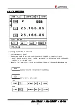
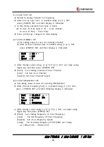
6.2   DSC  MENU  DISPLAY 

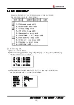
            Press  the〔MENU〕KEY  on  the  Initial  screen  of  the  DSC  MODE, 
            the  sub  menu  screen  is  set  as  follows  :


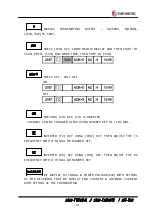
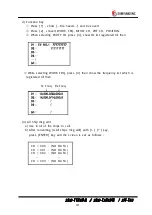
(1)  Distress  msg  edit
    a)  Use  in  a  call  of  distress. 
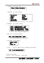
    b)  After  converting  [ 1.Distress  msg  edit]   with  [ ▲ ]   [ ▼ ]   key,  press  [ ENTER]   key
        and  the  screen  is  set  as  follows  :


CH  =  300

CH  =  301

CH  =  302

      ⋯

CH  =  399

:

:

:

:

(NO  DATA)

(NO  DATA)

(NO  DATA)

          ⋯

(NO  DATA)

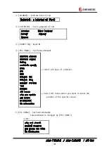
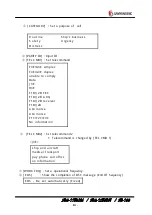
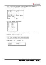
    c)  After  selecting  channel1  with  [ ▲ ] [ ▼ ] [ ◀ ] [ ▶ ]   key,  press  [ ENTER]   key
        and  the  message  edit  screen  is  set  as  follows.


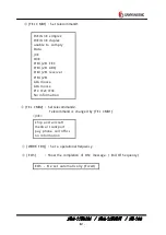
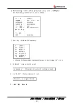
FORMAT

NATURE

POSITION

DIST-UTC

TEL  CMD

EOS

:

:

:

:

:

:

Distress

Undesigreted

N  .   E  .

:

J3E

EOS

Содержание SRG-1150DN

Страница 1: ...ID 50W LOW 250W HIGH 100W MID 50W LOW H3E 75W HIGH 16W LOW 75W HIGH 16W LOW F1B 100W HIGH MID 75W LOW 150W HIGH 100W MID 75W LOW 1 1 FEATURES 1 Possible range Because MF HF transceiver DSC W K receiver DSC Distress alarm telephone is built in SRG 1150DN SRG 1250DN you are able to use itself without NBDP terminal NBDP function works by connecting SN 100 TERMINAL but it is not available to use NBDP ...

Страница 2: ...tion SRG 1150DN SRG 1250DN consists of one unit therefore a large space is not required for operation SN 100 TERMINAL is able to use by connecting with SRG 1150DN SRG 1250DN cable 5 Trustworthy Adopted new DDS DIRECT DIGITAL SYNTHESIZE and improved the quality of sound trustworthy stability 6 Construction In order to endure in bad condition of marine environment hard aluminum body is manufactured ...

Страница 3: ...NAL SN 100 1 SET Assemble into SN 100 1 CONNECTION BOARD T 020 1 2 NBDP RECEIVER T 022 1 3 NBDP PLL T 023 1 4 POWER SUPPLY T 025 1 5 C PU BOARD MSC655S 1 3 HAND MIC SM 30 1 4 K EY BOARD SPR8630 1 5 ANTENNA TUNER SAT 100 1 6 POWER SUPPLY SP 1250ADC 1 7 PRINTER DPU 414 1 8 CONNECTION CABLE CON1250 1 9 SPARE PART INSTALLATION PART SPR1250 1 10 INSTRUCTION MANUAL INSTALLATION DIAGRAM 1 11 SPEAKER SS 1...

Страница 4: ...00 1SET Assemble into SN 100 1 CONNECTION BOARD T 020 1 2 NBDP RECEIVER T 022 1 3 NBDP PLL T 023 1 4 POWER SUPPLY T 025 1 5 CPU BOARD MSC655S 1 3 HAND MIC SM 30 1 4 KEY BOARD SPR8630 1 5 ANTENNA TUNER SAT 100 1 6 POWER SUPPLY SP 1250ADC 1 7 PRINTER DPU 414 1 8 CONNECTING CABLE CON1250 1 9 SPARE PART INSTALLATION PART SPR 1250 1 10 INSTRUCTIONAL MANUAL INSTALLATION DIAGRAM 1 11 SPEAKER SS 10W 4 1 1...

Страница 5: ...KHz H3E and 2187 5 4207 5 6312 8414 5 12557 16804 5KHz F1B is SCAN receiving all the time o Frequency Switching Time Between channels within 5 seconds Between bands within 15 seconds INCLUDE ANTENNA MATCHING TIME o Type of Emission USB J 3E H3E FSK F1B o Communication Method SIMPLEX and SEMI DUPLEX o Ambient Condition Temperature 15 55 Humidity 95 55 Oscillation full amplitude 3 2mm at 5 12 5Hz fu...

Страница 6: ...75 100 100W SRG 1250DN J 3E 50 100 250W F1B 75 100 150W 2182KHz H3E 16 75W o Type of Modulation Low power stage balanced modulation o Frequency Deflection Below 10Hz within 0 3ppm o Occupied Bandwidth J 3E Within 3KHz J 2B Within 0 5KHz o Carrier Attenuation 40dB or more at J 3E o Spurious Attenuation At J 3E 1 5 4 5KHz 31dB or more 4 5 7 5KHz 38dB or more 7 5KHz or more 43dB or more At F1B J 2B 1...

Страница 7: ...nna between 3 and 100 is 10 or less o Voice Output Max 5 6W or more o Receiving Sensitivity SSB is less than 3uV at freq 500KHz 29 9999MHz Only SSB S N D N D 20dB BAND width 3KHz output 100mW o Articulation 120Hz In case of DSC NBDP Symbol error rate at a receiver input voltage of 1 is 1 10 2 Only Receiving Mode FSK BAND width 0 3KHz a The detailed characteristics 3KHz FILTER for SSB The passband ...

Страница 8: ... times that of the wanted signal the symbol error rate is 1 10 2 or less o Selectivity suppression With a wanted signal of 10 and an unwanted signal that is effect than 3KHz from the wanted signal an unwanted signal input voltage of 10m suppresses the wanted signal output to 3dB In case of DSC NBDP With a wanted signal of 10 and 1 unwanted signal 500Hz from the want signal the character error rate...

Страница 9: ...270Hz 300Hz 30dB bandwidth within 380Hz 60dB bandwidth within 550Hz o Frequency Stability within 10Hz o SPURIOUS RESPONSE With a wanted signal of 10 and an 31 6 zero modulated interference signal which excludes the range within 750Hz of the wanted signal the character error rate is 1 10 2 or less o Spurious emission The power of emission from air antenna terminal is 4000 or less o Nominal input lo...

Страница 10: ...HT DISPLAY o INTERFACE RS 232 INTERFACE 2 CHANNEL equipment PRINTER INTERFACE 1 CHANNEL equipment based on CENTRONICS INTERFACE 2 7 DSC o PROTOCOL Complied with CCIR recommendation 493 3 and 541 2 o EMISSION F1B J 2B 100 BAUD o Modulator Output frequency 1700Hz 85Hz Output LEVEL Max 10dBm 600 ohm unbalanced balanced o Demodulator Input frequency 1700Hz 85Hz Input LEVEL 20dBm 5dBm 600 ohm unbalance...

Страница 11: ...r Correction one receiving station o Status Display POWER ON STAND BY CALLED CALLING FREE SIGNAL ARQ CFEC SFEC SEND RECEIVER PHASING REPHASING REPEAT ERR etc o Coding 7 bit code 4B 3Y constant ratio mark signal B 1785Hz Y 1615Hz o Memory Capacity 16M o System Parameter OPERATOR DATA is written on Flash Disk with Programming and Back up o Center Frequency 1700Hz o Frequency Shift Range 85Hz o Modul...

Страница 12: ...ward forward reverse logical seek 2 BIT IMAGE GRAPHICS MODE Total dots 8 320 dot line Line feed direction forward logical seek Length of a line 89 6mm Printing speed 52 5cps max standard size 80cps max reduced size Dimension 160mm 170mm 66 5mm Weight 580g approx Average life 500 500 line approx when print 8 40 characters fully with 100 darkness 3 AMBIENT Temperature 0 40 Humidity 30 80 RH at no co...

Страница 13: ...s o General Printer Characteristics Number of pins 9 No of multi part forms 4 one original 3 copies Print speed a t 12 c pi 10 cpi Super s peed 300 c ps High speed draft 240 cps Utility 200 c ps 200 cps Near letter quality 50 c ps 50 cps Fastest print s peed 300 cps Carriage width 10 c pi 80 columns Max in compressed mode 132 columns Dimens ions Heig ht 80 mm Width 360 mm D e pth 275 mm We ig ht 4...

Страница 14: ...n Characters re inking cartridge MT B F 6000 hours o Paper Handing S T ANDAR D OPTIONAL Autoload Single S heet Roll Paper Stand Platen in F eed Pull tractor feed Low tear off Single bin Sheet Feeder Paper end detection o Other options Optional ML 280 DC Voltage model for use with 12 of 25 DC power supplies for such applications as on the road printing in vehicles Paper path 1 Rear paper feed for c...

Страница 15: ...r operation instructions if a DSC distress or DSC alarm call is received 3 3 OPERATION BY DC POWER When AC power is disconnected the SRG 1250DN switches to the DC operation and the DC LED on MF HF control panel will light up automatically When it is transmitted to DSC AC signal will be changed to DC on upside of transceiver LCD display Moreover changing to DC mode will be displayed on downside of ...

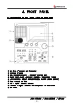
Страница 16: ...et of channels and frequencies INTERNAL SPEAKER MIC CONNECTION JACK CONNECT SUPPLED MIC FRONT PANEL LCD DISPLAYS CHANNEL FREQUENCY MODE ARTICULATION ADJUST ARTICULATION TO RECEIVE SIGNAL CLEARLY GAIN ADJUST AF GAIN VOL ADJUST SPEAKER VOLUME CHANNEL ADJUST CHANNEL AND FREQUENCY UP AND DOWN KEY PANEL ...

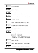
Страница 17: ...NSIDE LITHT 2 STEPS START AND FINISH CHANNEL SCAN RECEIVING US E FIGURE KEY INPUT PRESS KEY WITH ANOTHER KEY CAN BE FUNCTION UP FNC 7 N B ON OFF FNC 8 AGC ON OFF FNC 9 SQL ON OFF FNC 0 CHECK MODE RECEIVING RX SIGNAL OR POWER VOLTAGE 24V TRANSMITTING END CURRENT OR ANT CURRENT POWER ON OFF CANCEL SETTING OR RETURN TO PREVIOUS MENU TRANSMISSION MODE OF DISTRESS ALARM SIGNAL ...

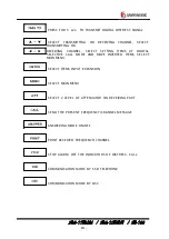
Страница 18: ...TEMS AT DIGITAL SELECTIVE CALL MODE AND MOVE INVERTED ITEMS S E LE C T MAIN MENU SELECT ITEMS INPUT EXPANSION SELECT MAIN MENU SELECT 2 LEVEL OF ATTENUATOR ON RECEIVING PART SEND THE PRESENT FREQUENCY CHANNEL MESSAGE ANSWERING MODE ON OFF PRINT RECEIVED FREQUENCY CHANNEL STOP ALARM OFF THE INDICATORS OF DISTRESS CALL COMMUNICATION MODE BY SSB TELEPHONE COMMUNICATION MODE BY DSC ...

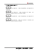
Страница 19: ...MITTING LED INDICATOR IS TURNED ON LED INDICATOR WHEN RECEIVING DSC SIGNAL LED INDICATOR IS TURNED ON EXCEPT OF DISTRESS SIGNAL LED INDICATOR WHILE TRANSMITTING LED INDICATOR IS TURNED ON LED INDICATOR WHEN W K RECEIVER IS ACTIVATED LED INDICATOR IS TURNED ON ALWAYS WORKING ...

Страница 20: ...ication MODE Frequency type of emission and transmitting POWER in transmitting part MODE BAND WIDTH AGC NOISE BLANKER ATTENUATOR AND S PE AKE R STATUS IN RECEIVING PRAT INDICATE KEY INPUT REFER TO OPERATION ITEMS IN COMMUNICATION MODE INDICATOR W K FREQUENCY SCANNING SPK KEY ON OFF ON OFF ...

Страница 21: ...CH PRESSING CH KEY CH IS INVERTED CHANNEL CAN BE CHANGED AFTER USING NUMBER KEY OF CH DIAL TX INVERTED TX KEY USING FRQ KEY THEN ADJ UST THE TX FREQUENCY WITH CH DIAL OR NUMBER KEY RX INVERTED RX KEY USING FRQ KEY THEN ADJ UST THE RX FREQUENCY WITH CH DIAL OR NUMBER KEY RxG 00 0 BE DISPLAY RX SIGNAL POWER VOLTAGE 24V WITH SETTING AT THE RECEIVING THAT BE DISPLAY END CURRENT ANTENNA CURRENT WITH SE...

Страница 22: ...display to change to DC when turn off AC POWER N B AFTER N B IS INVERTED USING FNC 7 KEY PRESS ENTER Key AND THEN ON OFF AGC ADJ UST INPUT SIGNAL AUTOMATICALLY AFTER AGC IS INVERTED USING FNC 8 KEY PRESS ENTER Key AND THEN ON OFF SQL AFTER SQL IS INVERTED USING FNC 9 KEY PRESS ENTER Key AND THEN ON OFF When setting up 2002 4 6 N 35 05 E 129 03 GPS DATA SIGNAL Lat Lot While changing channels indica...

Страница 23: ...can Frequency Set 4 SQL Set 5 LCD Contrast Set 6 TX POWER HIGH 7 Manual Tuning 8 ATU VERSION 9 SYSTEM SET DSC MAIN MENU 1 Distress msg edit 2 Individual msg edit 3 Group msg edit 4 All ship msg edit 5 Geography msg edit 6 Auto Semi AT msg edit 7 Dist ack rly msg edit 8 Ordinary ack msg edit 9 Display Send msg 0 System SET 2182 MAIN MENU ...

Страница 24: ...0 5 SSB RADIO TELEPHONE MODE 5 1 SELECT SSB MODE 1 Select by SSB KEY If pressing SSB KEY of FRONT PANEL set to SSB MODE as follows 5 2 SSB MENU DISPLAY If pressing MENU KEY at SSB mode display menu display is indicated as follows ...

Страница 25: ...ed 001 299 0 c After moving cursor using KEY set value using figure key and then press ENTER KEY d Start Set starting channel of Scan Channel Last Set last Scan Channel Speed Set Scan Channel Speed 3 SCAN FREQUENCY SET a Set setting value in case of scanning FREQUENCY b After 3 Scan Frequency Set is converted using KEY press ENTER KEY and then following display is indicated Start Last Speed Step 0...

Страница 26: ...y set Delay time of squelch circuit e Press CLR key changed to main display 5 LCD Contrast Set a Adjust LCD light and divided from 0 to 7 the higher setting value the darker b After move to 5 LCD Contrast Set using KEY press ENTER KEY and following display happens and then LCD light is changed FNC or LIGHT is able to be used also 6 TX Power Set a Adjust TX output b After 7 Tx Power Set is inverted...

Страница 27: ... 1 Tuning Clear using key press ENT key and display as follows If select Yes system is rebooting 2 SSB CH Clear Delete SSB channel data and set basic channel Revert 2 SSB CH Clear using key press ENT key and display as follows If select Yes system is rebooting 3 Data Set Set the date displayed on system 4 Time Set Set the time displayed on system 5 Key Tone Press ENT tone ON OFF 6 ADC Value RxG in...

Страница 28: ... Match all channels automatically Press ENT display as follows for each frequency by turns Freq Tune 2 032 0khz Tuning 8 Self Test Self test function Press ENT display as follows Version Receiver Watch R Exciter Tuner 2 0 good good good good ...

Страница 29: ...ALLING DSC MODE 6 1 THE SELECTION OF DSC MODE 1 selection by DSC key Press DSC key of the front panel DSC MODE is set CH1 C H6 In case of emergency only CH17 CH19 Can be used by user press SCAN key scan only in specified data location within CH17 CH19 ...

Страница 30: ...it a Use in a call of distress b After converting 1 Distress msg edit with key press ENTER key and the screen is set as follows CH 300 CH 301 CH 302 CH 399 NO DATA NO DATA NO DATA NO DATA c After selecting channel1 with key press ENTER key and the message edit screen is set as follows FORMAT NATURE POSITION DIST UTC TEL CMD EOS Distress Undesigreted N E J3E EOS ...

Страница 31: ...s Nxx xx North latitude 00 00 90 00 Sxx xx South latitude 00 00 90 00 Exxx xx East longitude 000 00 180 00 Wxxx xx West longitude 000 00 180 00 NOTE Do not out of the setting limit DIST UTC Set the time of distress xx xx Time of distress 00 00 23 59 Be set Automatically with the Input of GPS TEL CMD Set telecommand F3E G3E Simplex J3E F1B J2B Fec E OS Show the completion of DSC message End Of Sequ...

Страница 32: ...10 BY 10 UP DOWN c After selecting channel1 with key press ENTER key and the message edit screen is set as follows TX Freq FORMAT CATEGORY PARTY ID TEL CMD 1 TEL CMD 2 WORK FRQ 08 200 0 EOS 2 187 5 Individual Routine 000000000 J3E No information 08 200 0 Ack RQ TX Freq Indicate TX frequency 01 02 03 04 05 06 19 2 187 5 4 207 5 6 312 0 8 414 5 12 577 0 16 804 5 8 414 5 Indicate the frequencies whic...

Страница 33: ...G3E simplex F3E G3E duplex Polling unable to cpmply Data J3E H3E F1B J2B FEC F1B J2B ARQ F1B J2B receiver Test F1B J2B AIA morse ship pos update AIA morse F1C F2C F3C No information Select J 3E type of emission Select this menu when you want to know the position of the specific vessel TEL CMD2 Set Telecommand2 Telecommand is changed by TEL CMD 1 J 3E ship and aircraft medical transport pay phone c...

Страница 34: ...nd Of Frequency d Function Key Press 1 show File Saved and be saved Press 2 convert WORK FRQ MF HF CH VHF CH POSITION When selecting PARTY ID press 3 show ID list registered till then 01 S Y NO 1 777777777 02 111111111 03 04 50 While selecting WORK FRQ press 3 then show the frequency list which is registered till then T x F req R x F req 01 10 000 0 20 000 0 02 14 000 0 14 000 0 03 04 50 ...

Страница 35: ...lecting channel1 with key press ENTER key and the message edit screen is set as follows T X F req F OR MA T C A T E GOR Y PA R T Y ID T E L C MD 1 T E L C MD 2 WOR K F R Q 8 3000 0 E OS 2 187 5 Group R outine 000000000 J 3E No information 8 3000 0 E OS TX Freq Indicate TX frequency 01 02 03 04 05 06 19 2 187 5 4 207 5 6 312 0 8 414 5 12 577 0 16 804 5 8 414 5 Moreover indicate the frequency memori...

Страница 36: ... to comply Data J 3E H3E F 1B J 2B F E C F 1B J 2B A R Q F 1B J 2B receiver F 1B J 2B A IA mors e A IA mors e F 1C F 2C F 3C No information TEL CMD2 Sst telecommand2 Telecommand is changed by TEL CMD 1 J 3E s hip and aircraft medical trans port pay phone call offic s no information WORK FRQ Set a operational frequency E OS Show the completion of DSC message End Of Sequency E OS B e s et automatica...

Страница 37: ...show ID list registered till then While selecting WORK FRQ press 3 then show the frequency list which is registered till then Tx Freq Rx Freq 4 All Ship msg edit a Use in all of the ships to call b After converting 4 All ships msg edit with key press ENTER key and the screen is set as follows C H 300 C H 301 C H 302 C H 399 NO DA T A NO DA T A NO DA T A NO DA T A ...

Страница 38: ...D 2 WOR K F R Q E OS 2 187 5 A ll ship Dis tres s J 3E No information E OS TX Freq Indicate TX frequency 01 02 03 04 05 06 19 2 187 5 4 207 5 6 312 0 8 414 5 12 577 0 16 804 5 8 414 5 Indicate the frequencies memorized by user in DSC mode CH7 CH19 FORMAT Show a kind of a call A L L S hip S howing all of the s hips F ixed CATEGORY Set a purpose of call S a f e t y Urgency Dis tres s ...

Страница 39: ... F 1B J 2B receiver F 1B J 2B A IA mors e A IA mors e F 1C F 2C F 3C No information TEL CMD2 Set telecommand2 Telecommand is changed by TEL CMD1 J 3E ship and airc raft medical trans port pay phone call offics no information WORK FRQ Set a operational frequency E OS Show the completion of DSC message End Of Sequency E OS B e s et automatically F ixed ...

Страница 40: ...ON by turns When selecting PARTY ID press 3 show ID list registered till then While selecting WORK FRQ press 3 then show the frequency list which is registered till then Tx Freq Rx Freq 5 Geography msg edit a Use in a definite area b After converting 5 Geography msg edit with key press ENTER key and the screen is set as follows ...

Страница 41: ... 04 05 06 19 2 187 5 4 207 5 6 312 0 8 414 5 12 577 0 16 804 5 8 414 5 Indicate the frequencies memorized by user in DSC mode CH7 CH19 FORMAT Show a kind of call Geography S howing a areal call CATEGORY Set a purpose of call R o u t i n e S hip s bus ines s S a f e t y Urgency Dis tres s PARITY AD Input a definite area Nxx North latitude 00 90 S xx S outh latitude 00 90 E xx E as t longitude 000 1...

Страница 42: ... F 1B J 2B receiver F 1B J 2B A IA mors e A IA mors e F 1C F 2C F 3C No information TEL CMD2 Set telecommand2 Telecommand is changed by TEL CMD1 J 3E s hip and aircraft medical trans port pay phone call offic s no information WORK FRQ Set a operational frequency E OS Show the completion of DSC message End Of Sequency E OS B e s et automatically F ixed ...

Страница 43: ...hile selecting WORK FRQ press 3 then show the frequency list which is registered till then Tx Freq Rx Freq 01 10 000 0 20 000 0 02 14 000 0 14 000 0 03 04 50 6 Auto Semi AT msg edit a Use to contact with an aerial communication net b After converting 6 Auto Semi AT msg edit with key press ENTER key and the same screen is set as follows C H 300 C H 301 C H 302 C H 399 NO DA T A NO DA T A NO DA T A ...

Страница 44: ...T E L NO E OS 2 187 5 A T semi AT R outine 000000000 J 3E No information A ck R Q TX Freq Indicate TX frequency 01 02 03 04 05 06 19 2 187 5 4 207 5 6 312 0 8 414 5 12 577 0 16 804 5 8 414 5 Indicate the frequencies memorized by user in DSC mode CH7 CH19 FORMAT Show a kind of a call A T semi A T S howing A T s emi A T c alling F ixed CATEGORY Set a purpose of call R outine A us age F ixed PARITY I...

Страница 45: ...J 2B A IA mors e A IA mors e F 1C F 2C F 3C No information TEL CMD2 Set telecommand 2 Telecommand is changed by TEL CMD1 J 3E s hip and airc raft medic al trans port pay phone c all offic s no information WORK FRQ Set a operational frequency TEL NO Input a telephone number E OS Show the completion of DSC message End Of Sequency A C K R Q BE S E L E C T E D E S T A B L IS HE D ...

Страница 46: ...Press 2 convert WORK FRQ MF HF CH VHF CH POSITION by turns When selecting PARTY ID press 3 show ID list registered till then While selecting WORK FRQ press 3 then show the frequency list which is registered till then Tx Freq Rx Freq 01 10 000 0 20 000 0 02 14 000 0 14 000 0 03 04 50 ...

Страница 47: ...99 c Press 2 display as follows T X F req F OR MA T C A T E GOR Y PA R T Y ID T E L C MD PA R T Y A D DIS T ID NA T UR E POS IT ION DIS T UT C T E L CMD E OS 2 187 5 All ship Dis tres s 000000000 Dis tres s R elay N E D A DO unders ignated N E F 3E G3E S implex A ck R Q In case there is other vessel in distress or it s not able to send distress signal this function can be used instead of Distress ...

Страница 48: ...eography in case of all ship TEL C MD Selet telecommand In case of all ship Dis tres s A cK Dis tres s R elay In case let know the receiving the distress signal In case of relaying broadcast cause the distance is far from shore station PARTY AD Input specific area Group All ship individual DIST ID Input the ID of the vessel in distress NATURE Set the type of Distress F ire E x p l o s i o n F lood...

Страница 49: ...itude 00 00 90 00 E xx E as t longitude 000 00 180 00 Wxx Wes t longitude 000 00 180 00 DIST UTC Set the time of distress happened xx xx Dis tres s T ime 00 00 23 59 TEL CMD Set telecommand F 3E G3E S implex J 3E F 1B J 2B F ec E OS Show the completion of DSC message End Of Sequency E OS B e s et automatically F ixed ...

Страница 50: ...g edit a Can be use to common answer call b When press ENTER KEY after to invert 8 Ordinary ack msg edit by KEY be display as follows Display CH400 CH499 c Move channel 1 by 1 up down Move channel 10 by 10 up down d Able to answer pressing CALL key ...

Страница 51: ...screen c Move channel 1 by 1 up down Move channel 10 by 10 up down 10 SYSTEM SET a Decide the setting value manu of SYSTEM b Move cursor to 0 SYSTEM SET with KEY and press ENT key be display as following screen S elf ID S et Group ID S et Dis t T E L C MD J 3E LA T L ON S et ID F R T E L S et WK R S c an S et D a t a C lear ID Printing D a ta T rans mit Ds c E tc S et 123456789 011111111 ...

Страница 52: ... ID Operating frequency Auto answering ID Telephone No I D E DIT A uto A c k ID E DIT Work F requenc y E DIT T elephone No E DIT Ex Press ENT key on the line you want to edit display as follows Following display is selecting ID EDIT Press ENT key one more time display as follows Using keys select the spot you want then you can input 1 2 3 4 5 6 7 8 9 0 A B C D E F G H I J K L M N O P Q R S T U V W...

Страница 53: ...off 8414 5 on 12577 5 off 16804 5 off Using keys it can be ON OFF with pressing ENT on the frequency which you want But it is impossible to make 2187 5 and 8414 5 off Data Clear Delete the written data by user and received data DS C Made F ile clear DS C Dis tres s clear DS C Ordinary clear Maden DSC Data by user Distress data in the received DS C data Data expect Distress data in the received dat...

Страница 54: ... ON OFF While on if GPS signal is not receiving alarm rings every 1 min SCAN Speed Set Adjust SCAN Speed of usable DSC channel by user The higher number it is the slower speed Range is 0 9 Default Channel Adjust Tx Freq in DSC menu Select the frequency you want 2 187 5 4 207 5 6 312 0 8 414 5 12 577 0 16 804 5 Auto ACK Set off Press ENT ON OFF ON ACK O OFF ACK X Dist Key Test Test Distress key If ...

Страница 55: ...7 T R A NS MIT T E R OF D IS T R E S S S IGNA L 7 1 TEST OF DISTRESS ALERT SIGNAL a When press 2182 key of Front PANEL be display as follows b Only transmitting is not working in this mode c If you want to make test stop press STOP ...

Страница 56: ...STRESS ALERT SIGNAL a When press 2182 key of Front PANEL be display as following screen After revert DISTRESS SEND key transmit distress signal pressing ENT b If you want to make TX stop press STOP c Revert to SSB mode pressing SSB CHANNEL dial SSB key ...

Страница 57: ...AL a Press Distress Send button for 3 sec on front panel will be showed as follow screen Then Distress LED blink that means the position time ship ID will be sent Receiving channel range is from 1 to 6 as follows 01 02 03 04 05 06 2 187 5 4 207 5 6 312 0 8 414 5 12 577 0 16 804 5 ...

Страница 58: ...250DN SN 100 b If there is no answer it shows as follow screen After 3min 50sec Then it will try transmitting again from channel 1 through channel 6 till getting an answer c If you want to stop transmitting press STOP ...

Страница 59: ...hloride film for a long time Do not leave the paper in contact with freshly coped giazo type or wet process paper Do not allow the paper to come into contact with organic solvents b Caution when operate printer Check there is a paper in it before use Do not turn off while operation and turn off after PRINT HEAD is at HOME POSITION Printer test function is built in 2 Operation Panels a Power switch...

Страница 60: ...here is the wrinkle on the paper it may cause the paper jam PRINTER PAPER HANDLING b Switch off the printer c Open the PAPER COVER and pull out the center shaft d Insert the center shaft in the center of the PAPER ROLL and put the end of the paper into the way in of the paper e Switch of the PRINTER and press the FEED KEY until the paper is hauled f Store up the center shaft and the paper gets out...

Страница 61: ...nnected correctly If you are in any doubt consult a qualified electrician Operating your Printer Buttons Levers and Indicators Before using your printer it is worth familiarizing yourself with the buttons levers and indicators on the printer and to understand the various methods of loading paper The front panel of the printer has six buttons Also there are indicator lights that show the status of ...

Страница 62: ...er to the nest page Top Of Form press this button while the printer is deselected You can also select NLQ Near Letter Quality with this button J ust hold down the FORM FEED button while switching on the printer h ALARM Indicator Lights when paper supply is low or exhausted unless you use the command to disable the alarm Printing stops until the paper supply is replenished It is also lit when a jam...

Страница 63: ...way when using multi part paper 2 PAPER LOADING Bottom Feed Paper Loading a Place the printer on a slotted printer stand carefully aligning the slot in the stand with the opening in the base of the printer b Place the box of paper under the printer stand c remove the access cover and lift the column indicator bar d Open the paper release lever e Insert the first sheet of paper through the opening ...

Страница 64: ...ge the sprocket pins located on the platen ends g Turn the platen knob to advance the paper until it appears in front of the platen h Lower the column indicator bar I Close the paper release lever j Use the platen knob to advance the paper to the first printing line k Replace the access cover ...

Страница 65: ...no answer it do sending till getting an answer through CH1 to CH6 2 If you make transmitting stop press Reset key If distress signal is sent by mistakes contact to marine police or station SAR 9 2 IN CASE OF RECEIVING DISTRESS SIGNAL 1 Distress LED blinks and sounds bip Check contents displayed on the screen and press Reset key to stop 9 3 OPERATION BY DC POWER BATTERY 1 If AC power is turned off ...

Страница 66: ...MF HF DSC RADIO EQUIPMENT consists of circuit NBDP terminal SN 100 PRINTER ATU SAT 100 as follows RX ANT TX RX ANT SRG 1150DN SYSTEM Power Amplifier Circuit CONTROL Circuit DSC Circuit MF HF Transmitting Receiving Circuit W K Receiving Circuit Power Circuit NBDP SN 100 W K ATU SAT 100 PRINTER SRG 1150DN BLOCK DIAGRAM ...

Страница 67: ...m of this equipment s rear side there are aerial coaxial connector for MF HF transceiver coaxial connector for W K receiver connector for print connecting SPK J ACK or BK Connecting terminal ATU connecting CONNECTOR or earth terminal for system earthing 10 2 POWER CIRCUIT Power circuit consists of control circuit of power unit to turn on off DC 24V in power amplify unit constant voltage circuit to...

Страница 68: ... and pass LOW PASS FILTER This signal go to external RF AMPLIFIER and pass TX FILTER T 551 and go to POWER SPLITER T 516_1 and pass T1 T2 and is separated as PWR AMP A T 514 and PWR AMP B T 514 This signal go to TX PWR CONBINER T 516_2 and is combined and after go to DSC TX FILTER T 517 and amplify in the selected TX LOW PASS FILTER remove spurious and pass antenna terminal and go to ATU and match...

Страница 69: ...rom receiver inner circuit and supply in BK control circuit BK controling circuit control BK RELAY of input unit of high frequency and AGC circuit and protect receiver from over input Simultaneously have a muting receiving circuit Moreover it connect several connectors at rear side and do switching power supply of RX and TX a This circuit board incorporate through most circuit board to consist of ...

Страница 70: ...SRG 1150DN T 451 SRG 1250DN T 461 If TX 12V signal is not showed in the PCB circuit the main PCB T 454 and antenna are connected any time And if Tx signal is showed antenna is connected sith TX POWER SRG 1150DN T 514 SRG 1250DN T 524 through FILTER circuit At this time a filter is selected by transmitting frequency 10 7 SYNTHESIZER T 553 This circuit of PCB is divided to two part MF HF unit and W ...

Страница 71: ...perational Amplifiers IC3 AUDIO signal CONNECTOR 6PIN 5PIN connect PHONE J ACK through amplifier IC6 10 9 PA AMP SRG 1150DN T 514 SRG 1250DN T 524 This PCB circuit consists of TX output POWER AMP TX output is 150W SRG 1150DN and 250W SRG 1250DN 10 10 CONTROL T 557 This PCB circuit consists of CPU IC1 MEMORY ROM IC2 RAM IC3 CLOCK GENERATOR IC4 BUFFER IC5 I O AMPLIFY IC17 AC DC CONVERTER IC15 RS 232...

Страница 72: ...rmediate frequency 455KHz All local signal of receiver is supplied from DIGITAL CONTROL F R E QUE NC Y SYNTHESIZER through PHASE LOCKED LOOP PLL system and direct system to use 10MHz center oscillator supplied from DTCXO SSB GENERATOR circuit a Receiving signal in ANTENNA terminal pass BK RELAY and input and voltage protecting circuit and pass band pass filter and is closing in DSC distress safety...

Страница 73: ...posed of FILTER circuit mixing circuit or micro processor for DOT PATTE RN J UDGE a FILTER CIRCUIT is receiving 2KHZ 8 LOW PASS SC FILTER Each transmitted signal is to be limited and is sent to judging circuit of DOT PATTE RN In judging circuit of DOT PATTERN is mixed like Software every 10mS MASK SPACE MASK SPACE 1 0 mS 1 0 mS 1 0 mS 10mS DOT PATTERN MICRO COMPUTER do a sampling signal transmitte...

Страница 74: ... TIMING OF DOT DET SIGNAL and RESET SIGNAL 10 13 FUNCTION DIAGRAM OF REAR SIDE CONNECTOR TO CONNECT PRINTER POWER 8V GPS DATA BK CONNECTOR ATT AND ETC MF HF ANT IMPEDANCE 50 75Ω MF HF RECEIVING ANTENNA INPUT J ACK ATU ATU CONTROL CONNECTOR EXT J ACK EXTERNAL SPEAKER CONNECTING J ACK W K ANT IMPEDANCE 50 75Ω W K RECEIVING ANTENNA J ACK CAR CONNECTOR SUPPLY CONNECTOR FOR EQUIPMENT POWER ...

Страница 75: ...USE 30A FUSE GND RECEIVER SYSTEM GROUND PRINTER PRINTER CONNECTOR ALARM BOX CONNECTOR WHICH WITH CONNECTED WITH SD 250 AC DC DETECTOR POWER UNIT AC DC DETECTION TERMINAL CONTROL CONNECTOR BETWEEN SRG 1150DN SRG 1250DN AND SN 100 NBDP TERMINAL ...

Страница 76: ...AIN UNIT FRONT PANEL LCD CHANNEL TX RX FREQUENCY RF GAIN CLARIFY ATT AGC AND FUNCTION KEYS ARE DISPLAYED SPEAKER ALARM RINGS WHEN IT RECEIVES DATA OR WARNING SIGNAL TX LED RED LIGHT ON TX LED RX LED GREEN LIGHT BLINKS WHILE RECEIVING DATA POWER SWITCH SN 100 POWER ON OFF ...

Страница 77: ...and present channel TX Set transmitting frequency RX Set receiving frequency BAR GRAPH Indicate adjusting portion as Bar Graph RF GAIN Adjust the portion of RF GAIN properly using up down with direction keys 0 1steps CLARIFY Adjust the number properly using up down direction key 10Hz ATT Adjust attenuator 4 steps using up down direction key ...

Страница 78: ...TX Set Tx frequency RX Set Rx frequency TUNE is used when user want to do matching to antenna MENU Indicate Main Menu ARQ Communicate with Automatic Repeat Request Mode FEC Communicate with 1 way Forward Error Correction Station Edit Register the frequency of the other station Station Print Print out the frequency of registered the other station Macro Command Write Macro command Editor Edit file a...

Страница 79: ...to forward channel of it 11 3 SETTING UP TX RX FREQUENCY UNIT kHz 1 Setting Tx frequency a Press F7 key on the keyboard b Input the frequency with number key While inputting frequency if press curser will move c Press ENT NOTE Available TX Freq range 1 6MHz 27 5MHz 2 Setting Rx frequency a Press F8 key b Input the frequency with number key While inputting frequency if press curser will move c Pres...

Страница 80: ...s followings b Revert the other station you want to communicate using key And then press ENT key display as followings c Revert the channel you want to communicate using key And then press ENT key Set TX RX frequency to registered freq on channel displaying the first display of NBDP ...

Страница 81: ...nel with Number keys c Press ENT key 11 4 ARQ MODE 1 Connecting with the other station by ARQ mode Connecting by present adjusting channel a Press F2 key displaying as following screen b Select ARQ and press ENT then it will be connected with other party through ARG mode in present setting Channel ...

Страница 82: ...SRG 1150DN SRG 1250DN SN 100 Connecting specific station a Call the menu pressing F10 to call SUB MENU b Select ARQ from the above menu press ENT then display the screen as follow ...

Страница 83: ...ng ESC key d Select the channel you want to use with key then press ENT e Call the other station with selected frequency displaying next ARQ mode first display If you want to make calling stop can be back to the Telex first display by pressing F8 f In case that the connecting is done properly you can see the curser in the left up side of the screen ...

Страница 84: ...glish Russian NOTE It is possible while the present language is Russian only F1 WHU Demand Answer back code of the other station F2 Hereis Transmit Answer back code of yourself F3 TMS Transmit the present time F4 F Send Transmit the file written in edit mode Refer to 4 TX of file F5 Macro Transmit Macro Command F7 Over Convert the direction of transmitting the message F8 Stop Stop communication F9...

Страница 85: ...0DN SN 100 11 5 FEC MODE 1 Connecting the other station by Selective FEC mode Communication with present selecting Channel a Press F2 and display screen as below b Select FEC and press ENT then below screen is displayed ...

Страница 86: ...yed To be back to forward display press CLR key d After selecting the channel press ENT key e Can call the other station in the channel you selected displaying the first screen in SFEC mode To stop calling press F8 f As long as connecting with the other station a curser will be displayed on the left up side of the screen ...

Страница 87: ...SRG 1150DN SRG 1250DN SN 100 2 Connecting with the other station by collective FEC mode a Call SUB menu with pressing F10 b After selecting FEC press ENT key Then follow display is showed ...

Страница 88: ...e FEC mode first display is showed Communication is available under this condition b After typing message with keyboard press ENT to send Back space Delete one character on the left side Transmitting is not available unless you press ENT key c To use each function press function keys d Can transmitting Macro command written in F5 4 Usable keys in FEC mode The usable characters ABCDEFGHIJ KLMNOPQRS...

Страница 89: ... 2 follow the operation as below a Press F4 and below screen is displayed b After selecting the file using key press ENT c Can be transmitted displaying the contents of the file on the screen Pressing F8 key is able to stop transmitting 6 Transmitting of Macro Command After done 1 or 2 follow the operation below a Press F5 b After selecting the command press ENT c Can be transmitted displaying con...

Страница 90: ...SRG 1150DN SRG 1250DN SN 100 11 6 OTHER SEA STATION OR SHIP STATION EDIT RESISTER FREQUENCY a Call the SUB menu pressing F10 b After selecting Station Edit press ENT Then following is displayed ...

Страница 91: ...er selecting station press ENT e After inputting name of Station press ENT f After selecting ID press ENT g After inputting ID press ENT h After selecting the channel press ENT i After inputting Tx Freq press ENT j After selecting Rx channel press ENT k After inputting Rx Freq press ENT l Press ESC key to change to the first display ...

Страница 92: ...TION PRINT a Call the SUB menu pressing F10 b After selecting Station Print press ENT Then following is displayed c After selecting the other station you want to communicate press ENT Then selected frequency of the other station is printed ...

Страница 93: ...0 11 8 REGISTRATION OF MACRO COMMAND a Call the SUB menu pressing F10 b After selecting Macro Command press ENT Then the following is displayed c Select the number of Command using d After inputting Command by keyboard press ENT ...

Страница 94: ...DN SRG 1250DN SN 100 11 9 EDITOR MODE a Call the SUB menu pressing F10 b Select Editor and press ENT then following screen is displayed c Writing and modifying contents is possible In order to finish press ENT ...

Страница 95: ...F10 b After selecting System set pressing ENT Then the following is displayed 0 ARQ FEC 4 or 5 digit ID 1 ARQ FEC 9 digit ID 2 Answer Back Code 3 Collective FEC Receiving 4 Maximum FEC Error Ratio 5 NAVTEX Station Selection 6 NAVTEX Message Selection 7 NAVTEX ID Data Clear 8 ID Printing 9 Etc Setting ...

Страница 96: ...te the procedure as below a Select Maximum FEC and press ENT b While receiving letters in FEC mode if error ratio is over specific setting rate receiving is stoped automatically Ex If it is set as 30 when error ratio is over 30 and receiving is stoped Setting of ARQ FEC 4 or 5 digit ID It is fixed when the equipment is set It s impossible to change by user 6 Selecting NAVTEX STATION After doing as...

Страница 97: ...D Printing b Press ENT to print ID of yourself 10 Etc Setting After done above 1 follow the operation below a Select Etc Setting and press ENT Then below screen is displayed b In order to reset the menu press ENT 0 Language Can select the language among KOR ENG RUSSIAN 1 Printer Type OKI printer or DPU 414 2 Printer Poter Local printing from main unit or REMOTE printing from terminal 3 Date Set Se...

Страница 98: ... sec 2 Space transmission Transmitting signal of 1 7KHz 85Hz for 40 sec 3 Dot transmission Transmitting signal of 1 7KHz 85Hz for 40 sec 4 Printer Test Check printer condition by doing test printing 5 NBDP Rx Tx Test Check NBDP terminal condition by transceiving the signal 6 Freq Shift Correct The function which receiving 14MHz 1400Hz from receiving terminal and correct terminal 1st LOCAL frequenc...

Страница 99: ...e function of Freq Shift Correct Main unit and Terminal unit should be pre heated Test NBDP RX TX and check it is O K Check Freq Freq Shift View 11 12 LCD OFF a Call the SUB menu with pressing F10 Then the following as display b To off LCD select LCD Off and press ENT c Even LCD is turned off other functions are available and if key is pressed or receive the data then LCD is turned on ...

Страница 100: ...NNECTION BOARD T 020 T 020 is PCB which is connecting CPU BOARD and other PCBs 12 3 NBDP Receiving unit T 022 T 022 PCB is NBDP receiving unit which consists of frequency filter and amplifier MIXER ATT AGC B K control circuit 12 4 PLL BOARD T 023 T 023 is SYNTHERSIZER PLL PCB 12 5 POWER CIRCUIT T 025 Power circuit consists of constant voltage circuit And while power on it makes ON main power DC 24...

Страница 101: ...CH SEND W K SIGNAL RECEIVED FROM RX ANT IN TO MAIN UNIT KEYBOARD CONNECT BETWEEN KEYBOARD AND SN 100 SUPPLY 5V DATA CLK ETC GND RECEIVER SYSTEM GROUND FUSE 5A FUSE PRINTER 24V FUSE PRINTER CONNECT TO PRINTER PRINTER POWER CONNECTOR WHICH SUPPLIES 24V 8V GND TO PRINTER FUSE 3A FUSE POWER SUPPLY FUSE CONNECTOR TO MAIN UNIT TRANSCEIVING PTT IN PTT OUT READY DATA AF AF ...

Страница 102: ...hat don t need to be delicated ohm voltage current 2 TEST PROBE that can be change from high frequency signal to direct current 3 high frequency transit power supply that can be check of travelling wave of until 1 6MHz 27 5MHz band max 150W 500W 4 100MHz band max 150W dummy load of 50Ω 5 Frequency counter that can be check 100MHz band 6 OSCILLOSCOPE that can be check 100MHz band 7 other testers 13...

Страница 103: ...B it s badness 3 TRANSMITTER Check follow as when hand set is correct when transmitter switch hand set can t receiver at the operating check the connecting condition a Check Air antenna power can t receiver when channel selecting is incorrect or selected unpermitted channel b Check T 514 SRG 1150DN T 524 SRG 1250DN and T 451 SRG 1150DN T 461 SRG 1250DN PCB if this part is not good have to change c...

Страница 104: ...N 1 In case of checking transmitter unit please contact dummy load 2 In case of separating each PCB pay attention to static electronic 3 In case of modulating use tools for modulation 4 In case of checking or modulating when measuring instrument contact in each circuit user should match signal of the circuit and PROBE of measuring instrument 5 In case of checking or modulating pay attention to the...

Отзывы: