


10
Pre-Operating Procedures cont’d ...
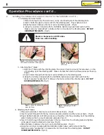
2. Before operating the fl oor stripper, perform the following
environmental
checks:
a. Is the work area free and clear of damp areas, leaks, fl ammable substances, electrical hazards, or
any other similar conditions?
b. Are there any standing pools of water or other conductive liquids and materials that can interfere
with the safe operation of the machine at the jobsite?
c. Has the work area been cleared of debris such as rags, string, wire, rocks, metal and other materials?
Such items could cause malfunction or damage to the fl oor stripper that could also be potentially
hazardous to the machine and operator.
d.
Voltage
Warning:
Before connecting the tool to a power source, verify that the voltage supplied is
equal to 120V. A power source whose voltage is greater than that specifi ed for the operation of the
tool can cause serious injury to the operator, as well as damaging the machine. If in doubt, DO NOT
CONNECT THE MACHINE TO THE UNKNOWN POWER SUPPLY.
e. Is there a reliable source of grounded electricity available? Use only GFCI receptacles.
f. If using an extension cord, is it in good condition and conforming to local safety codes?
Extension cords must be a 3-pole cord with a 3-pole plug and socket, rated for outdoor use. Our
recommendation is as follows:
A. Up to 100’ ft. = 14 AWG
B. Up to 200’ ft. = 12 AWG
C. Up to 300’ ft. = 10 AWG
D. Up to 400’ ft. = 8 AWG
Operating Procedures
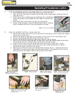
A.
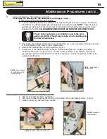
Installing the blades and support mounts for the SAMURAI
1. Ensure that the fl oor stripper is completely turned off, cooled, and at a complete stop prior to adjusting or
relocating the unit. Disconnect unit from power source.
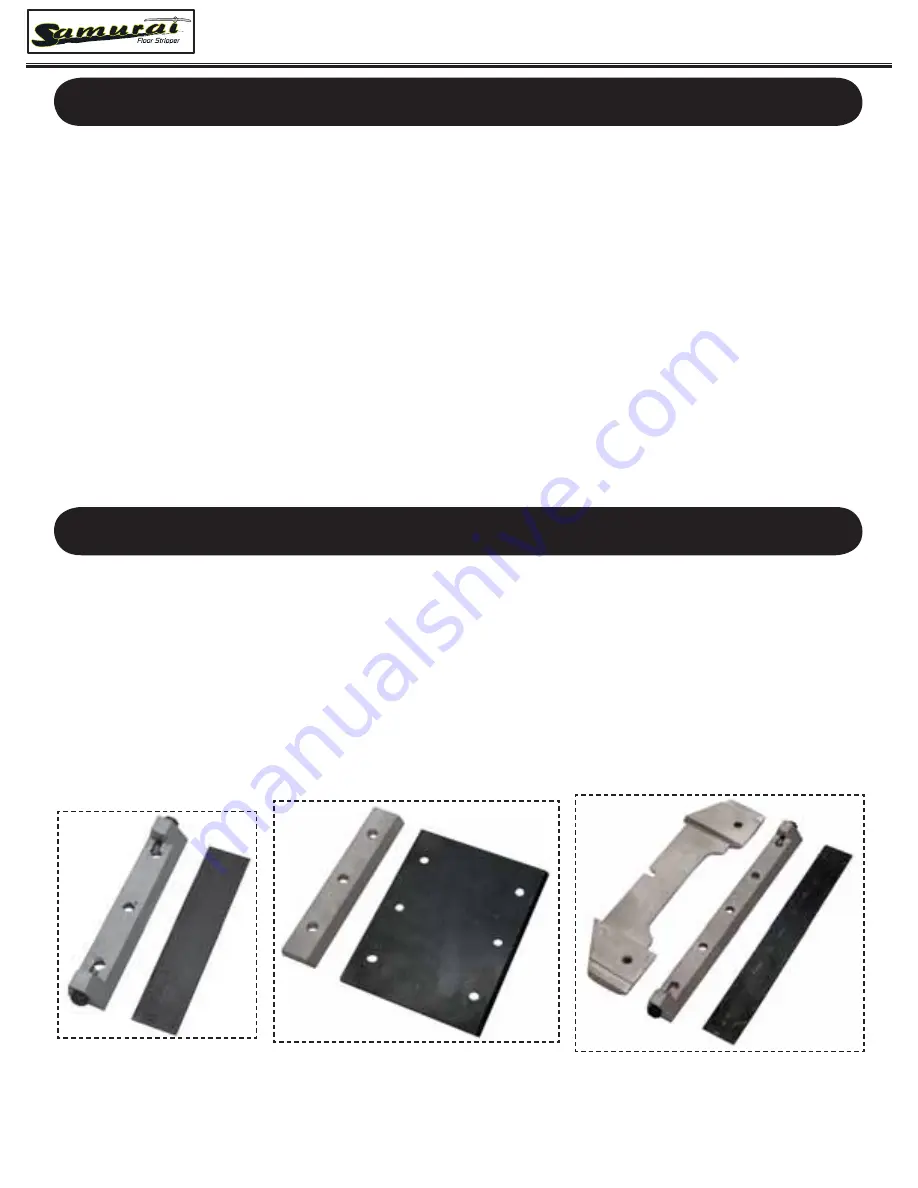
2. Select the appropriate blade and mount required. Both the
4” parquet fl ooring blade and the 5-3/8”
multi-purpose blade (ideal for stairs) are used with different 3-hole top mounts. The 9”
blade requires
both the 5-hole top mount and the matching plate extender.
See Figs. 1, 2, & 3 to ensure that the
appropriate mounts are matched to the proper blade.
Remove corresponding quantity of bolts for
mounting.
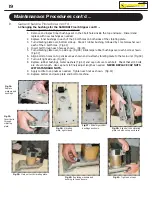
3. Place the unit, blade(s), support mount(s) and bolts on a clean and sturdy work bench. Due to the
weight of the unit and the sharpness of the blades, NEVER perform any adjustments to the fl oor stripper
without proper support. Failure to do so may lead to severe bodily harm, jobsite and machine damage.
Fig.1:
Support mount and
5-3/8” multi-purpose blade
Fig.2:
Support mount and
4” parquet blade
Fig.3:
Support mount and
9” multi-purpose blade


