Removal and Reassembly _ 17
No.
Part
Description
Figuer
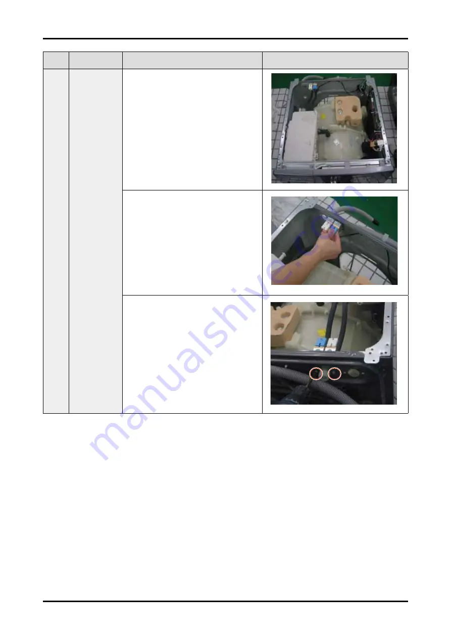
04
WATER
SUPPLY
VALVE
1. Remove the top-cover.
2. Separate the water supply
valve wire.
3. Remove the 2 screws holding
the water supply valve.
Страница 1: ...el Name WF706U2SA SEINE PROJECT Model Code WF706U2SAWQ TL SEINE PROJECT Refer to the service manual in the GSPN see the rear cover for the more information 1 Safety Instructions 2 Features and Specifications 3 Disassembly and Reassembly 4 Troubleshooting 5 PCB Diagram 6 Wiring Diagram 7 Schematic Diagram 8 Reference ...
Страница 2: ... Tools for disassembly and reassembly 13 3 2 Standard disassembly drawings 14 4 Troubleshooting 33 4 1 Error modes 33 4 2 Corrective actions for each error code 37 5 PCB diagram 44 5 1 Main PCB 44 5 2 Circuit diagrams of main parts for main PCB 45 5 3 Sub PCB 46 5 4 Detailed descriptions of contact terminals for sub PCB 47 6 Wiring diagram 48 6 1 Wiring diagram 48 7 Schematic diagram 49 7 1 Main c...
Страница 3: ...ure to disconnect the power plug before servicing Failing to do so may result in a risk of electric shock Do not allow consumers to connect several appliances to a single power outlet at the same time There is a risk of fire due to overheating When removing the power cord make sure to hold the power plug when pulling the plug from the outlet Failing to do so may damage the plug and result in fire ...
Страница 4: ...akage AFTER SERVICING Check the wiring Ensure that no wire touches a rotating part or a sharpened part of the electrical harness Check for any water leakage Perform a test run for the washing machine using the standard course and check whether there is any water leakage through the floor section or the pipes Do not allow consumers to repair or service any part of the washing machine themselves Thi...
Страница 5: ... not press a control button using a sharp tool or object This may result in electric shock or damage to the product WHILE SERVICING When wiring a harness make sure to seal it completely so no liquid can enter Make sure that they do not break when force is exerted Check if there is any residue that shows that liquid entered the electric parts or harnesses If any liquid has entered into a part repla...
Страница 6: ...rom the power outlet and measure the insulation resistance between the power plug and the grounding wire of the washing machine The value must be greater than 10MΩ when measured with a 500V DC Megger Check whether the washing machine is level in relationship with the floor Check whether it is installed firmly on the floor Vibrations can shorten the lifetime of the product CAUTION ...
Страница 7: ...mance has increased but potential damage to the washing has been minimized The size of the holes on the diamond drum has been reduced for minimizing damage to the washing The embossed wall of the drum serves as a washboard dramatically increasing the washing performance compared with existing drum washing machines which use the power of the difference in elevation only The size of holes has been r...
Страница 8: ...per energy saving the detergent infused bubbles penetrate the fabrics much faster and efficiently than for a conventional wash system delivering a cleaner wash performance especially for colder temperature cycles The lower the water temperature of the cycle the greater the impact of using Eco Bubble versus conventional systems this allowing more use of colder wash cycles and helping to save energy...
Страница 9: ...ry when it is humid the machine can dry it within 30 minutes Preventing bio film caused by humidity from occurring You do not need to worry about the humidity inside the drum The drum is dried regularly preventing bio film Water Safety System The Water Safety System has invented for perfect leakage protection The double safety valve connects directly to the water faucet In the event of a leakage t...
Страница 10: ... Makes Shapeless Garments a Thing of the Past High temperatures and harsh bleaches can damage and discolor your clothes The Ag Silver Nano Technology helps your clothes last longer without stretching shrinking pilling or fading Ceramic Heater The ceramic heater in Samsung washing machine prevents metals in hard water from being attach to the heater which may cause a reduction in heater efficiency ...
Страница 11: ... your washing machine This is especially true for machines that require a lot of energy Samsung s Volt Control guarantees that your washing machine works safely even with voltage deviations of 25 What does the Volt Control mean This is technology that allows to safe a washing machine from high shock and even lower voltage There is an additional protective measure in a washing machine for your prec...
Страница 12: ...ash Type FRONT LOADING TYPE Dimension 600mm x 550mm x 850mm Water Pressure 50 kPa 800 kPa Annual water consumption AW_c 2 9400 ℓ yr Weight 61 kg Wash Spin Capacity 7 0 kg Power Consumption WASHING and HEATING 220 240 V 2000 2400 W Spin Revolution Max rpm 1200 600 550 850 ...
Страница 13: ... logic Weight Detection 3 Stages 3 Stages Heater Capacity 2000 W 230 V 2000 W 230 V Water Supply Cold only Cold and Hot Drainage Pump Pump Power outage Compensation Yes Yes Zero Standby Power Yes 0 5W or Less Yes 1W or Less USP Voltage Protector Yes Yes Air Refresh No No Silver Wash No No Water Safety No No Ceramic Heater Yes Yes Diamond Drum Yes Yes Loading Entry Size Wide 308 mm Wide 308 mm Desi...
Страница 14: ...only MANUAL USERS DC68 03178F 1 Default CAP FIXER DC67 00307A 4 Default HOSE HANGER DC62 10278A Default Note is supplied for specific models only among those without water supply hoses You can purchase additional water supply and drain hoses from a service center For built in models the spanner water supply and drain hoses are not supplied Both the water supply and drain hoses are supplied during ...
Страница 15: ...ew 5 Motor 2 Balance 9 13mm Shock Absorber 2 holes each in left right Damper 2 Damper friction 2 19mm Pulley 1 Double ended spanner 10mm 13mm 19mm Replaced by box driver Vice pliers A Tool for protecting empty turning of bolt or abrasion from using box driver For disassembly of Spin drum Others screwdriver nipper long nose pliers Common tools for servicing ...
Страница 16: ...reference when disassembling and reassembling the product No Part Description Figure 01 ASSY COVER TOP 1 Remove the two screws holding the Top Cover at the back of the unit 2 Remove the top cover by lifting it up after pulling it back about 15mm 3 Then the Water Pressure Sensor Noise Filter and Water Valve can be replaced Sensor pressure Water valve Noise filter ...
Страница 17: ...ont operating panel 2 Remove the two screws at the top of the ASSY PANEL CONTROL 3 Hold the ASSY PANEL CONTROL while pulling it upwards and release the hook to remove it 4 Disconnect the terminals connected to the PCB by hand 5 Hold the ASSY PANEL CONTROL while pulling it upwards and release the hook to remove it ...
Страница 18: ...CB 1 There are six clasps to fix pcb such as the right picture shows 2 Press the clasp release the clasp and then press clasp release the clasp after that press clasp and release the clasp from upwards 3 Finally take the PCB out from right claps 4 Repair or replacement ...
Страница 19: ...Removal and Reassembly _ 17 No Part Description Figuer 04 WATER SUPPLY VALVE 1 Remove the top cover 2 Separate the water supply valve wire 3 Remove the 2 screws holding the water supply valve ...
Страница 20: ...he Water Hose to the main body of the Pressure Switch 2 Fix the Hose Clamper 3 Place the Pressure Switch into the Bracket Hole holding the main body of the Pressure Switch 4 To separate the Pressure Switch pull the Pressure Switch forwards while pushing the marked part with your finger ...
Страница 21: ...Seperate top cover 2 Seperate filter net wire 3 Remove the nut 4 Replace filter net 07 DOOR HINGE 1 Open the door removing the two screws holding the door hinge and sep erate the door 2 Remove the 11 screws holding the Holder Glass separate the Holder Glass and replace the hinge ...
Страница 22: ...e the spring from the lower part of the Diaphragm with a screwdriver Since the Diaphragm can be damaged when removing it remove it slowly in one direction 3 Remove the assy clamp diaphgram as photo graph 4 Remove the two crews 5 Remove the screw hold ing the Door Lock S W Remove the Door Lock S W Remove the connec tion wire Remove the connec tor after releasing it by pressing the catch ...
Страница 23: ...ly _ 21 No Part Description Figure 09 FRAME FRONT 1 Remove the two screws holding the frame front 2 Remove the three screws holding the bottom of the frame front 3 The door diaphragm pump shock damper and door lock switch ...
Страница 24: ...er of the Pulley Assembling the belt Place the belt around the Pulley and then over the Motor Pulley 12 MOTOR 1 Separate the Wire Housing from the motor 2 Remove the two bolts holding the motor at the back of the washing machine The 2 screws designated A which are inside must be also removed 3 Separate the motor When installing the Belt around the Motor Pulley the bottom of the belt must be locate...
Страница 25: ... driver into the upper part of the Filter Cover and push it downwards to release the catch 2 Remove the remaining water through the drain age hose Place a bowl under the drainage hose or the remaining water may fl ow out 3 Remove the screw hold ing the Drain Pump 4 Release all band rings 5 Seprate the connection wire ...
Страница 26: ...in and replace it Check Points for Troubleshooting 1 Separate the Drain Filter and check if any alien substances are inside the pump e g coins buttons etc Remove these if found 2 Check if the wire driving the pump is has come loose Take the relevant countermeasure if necessary 3 When water leaks check the assembly status of the Clamp Hose and Cap Drain Take the relevant countermeasure if necessary...
Страница 27: ...Removal and Reassembly _ 25 No Part name Description Figure 14 DAMPER 1 Remove the top screw shown in the figure from back 2 Remove the following screw shown in the figure from front Seprate the damper ...
Страница 28: ...1 Remove the three screws 3 Remove the three screws 4 Separate the WEIGHT BALANCE F For disassembly please make sure assembled the BRACKET NUT into the TUB first Make sure the hole and hole respond to each other correctly There is no ringt and left direction for WEIGHT BALANCE F ...
Страница 29: ...scription Figure 16 HOSE FILTER TUB 1 Disassembling and Reassembling the Hose Joint Clamper 17 HEATER 1 Separate the Back Cover 2 Separate the Connection Housing 3 3 Remove the nut and the screw holding the cover heater Separate the cover heater ...
Страница 30: ...correct position of the bracket inside the Tub when reassembling it Otherwise there is a danger of a fire Make sure to push it inwards until the packing part comes into the Tub completely when reassembling it so that the packing part is completely stuck to the Tub Fasten the holding nut with a force of 5Kgf cm2 If the nut is not fastened properly there is a danger of water leaking ...
Страница 31: ...ER 1 Insert the vertical hook of SPRINGHANGER into the GUIDE SPRING on the ASSY FRAME 2 Drag the SPRING HANGER to insert the elliptical hook into the hole that s at the side of the ASSY TUB as the left picture show 3 Make sure the SPRING HANGER s two hooks are assembled right ...
Страница 32: ...Description Figure 19 ASSY TUB 1 Remove the 14 screws holding the tub 2 Separate the ASSY BOLT on the BACK TUB 3 Separate the PULLEY 4 Separate the ASSY DRUM 20 PACKING TUB 1 Assemble packing tub s one side of 凹 to TUB BACK use two hands ...
Страница 33: ...t Description Figure 21 OIL SEAL 1 Assemble the OIL SEAL in the TUB BACK 2 Press the OIL SEAL gently and turn it back and forth 22 ASSY DRUM 3 Remove the WASHER WAVE from the SHAFT 4 Remove the three screws holding the ASSY FLANGE SHAFT ...
Страница 34: ...32 _ Removal and Reassembly No Part Description Figure 23 ASSY DRUM 1 Remove the one screw holding the DRUM LIFTER 2 Release the HOOK 3 Assemble the HOOK DRUM BACK Holding it with screw ...
Страница 35: ... The motor hall sensor terminal is not connected PBA fault For USA products this error occurs when an interference is generated due to too much laundry etc 3E2 3E2 The motor driving error from the PBA is weak Unstable relay operation etc 3E3 3E3 bE This occurs due to erroneous operating signals for the motor hall sensor The IPM terminal of the main PBA is not connected The DD motor cover is out of...
Страница 36: ...Check the voltages An error occurs when under or over voltage is supplied Check whether a plug receptacle is used When the connecting wire is 1m a momentary low voltage may drop up to 10 V Main PBA fault sometimes For Full Automated products no error code is displayed for a power error 9E2 Plo PF This error is not a fault but occurs during a momentary power failure If started again when this error...
Страница 37: ...ents a thermal sensor error or any misuse of the unit If this error occurs for another reason it is due to a washing heater sensor fault Replace it Door Error dE door dE Ed door dS Before operation dE A switch contact error because of a deformation of the door hook When the door is pulled by force When the door is not opened after the door open operation dL During operation This occurs in the Boil...
Страница 38: ...oducts Check whether the product is a steam model Water Leakage Error LE LE1 11E E9 LE LE Heater engagement fault out of place The air hose is out of place and water leakage occurs during the spin cycle The tub back at the safety bolts fixing part is broken Water leakage occurs at the front with foaming because of too much detergent Water leakage occurs because the connecting hose to the detergent...
Страница 39: ...mperature sensor fault for models before the silver nano function was applied tE3 tE3 This occurs when the duct condensing temperature sensor is open This occurs when the duct condensing temperature sensor has a wire disconnected or is short circuited The connector is out of place or has a contact error Dry heater temperature sensor fault for models before the silver nano function was applied Unba...
Страница 40: ...ror 3E 3E1 3E2 3E3 3E4 Washing motor fault Washing motor hall sensor fault Incorrect connections of the washing motor hall sensor connector Washing motor rotor and stator fault Main PCB fault Check the motor connector terminal connections and contacts 3E1 is displayed because overloading occurs due to too much laundry If the hall sensor terminal is faulty replace the hall sensor Check whether the ...
Страница 41: ...hether the revolutions of the drain pump motor are restrained by foreign material Check the same thing for the natural drain process Check whether the connections are correct and if there is any wires disconnected If the drain pump operates abnormally intermittently when the temperature of the water in the tub is high If the motor revolutions are restrained due to freezing in the winter season che...
Страница 42: ...ror in the connections replace the main PBA GAP Check the contact between the control panel buttons and their corresponding tact switch There must be a gap between a control panel button and its corresponding micro switch Otherwise an error occurs after approx 30 seconds has passed Cooling Error CE Washing temperature sensor fault Description of PL hazard prevention This error occurs if the water ...
Страница 43: ...or switch voltage Check the voltage after the power is on That is check the door switch when the power button is turned on and no operating key is pressed TYPE 2 The resistance of Nos 3 and 5 of the DOOR LOCK SWITCH must be approximately 949 Ω Dry Duct Fan Error FE Dry duct fan motor fault Main PCB fault Check for disconnected wires and insulation defects for the dry motor Check connector connecti...
Страница 44: ...lve and Tub connections and take any required action For natural draining this error occurs because the drain bellows are clogged with foreign material Remove the foreign material Check the drain motor operation Replace if it does not operate normally DRAIN PUMP TYPE Automatic Drainage Check whether there is any foreign material in the bellows Check for any foreign material such as underwear wires...
Страница 45: ...ce it A tE1 error occurs Check the connections for the dry heater temperature sensor connector If the dry heater temperature sensor has a functional error replace it A tE2 error occurs Check the connections for the duct condensing temperature sensor connector If the duct condensing temperature sensor has a functional error replace it A tE3 error occurs Unbalance Error UE Motor hall sensor fault Ca...
Страница 46: ...ACV to operate the PBA 2 RY3 Heater Realy For driving the heater power 3 CN1 Water Level and Thermal Sensor Connection Terminal Detect the water supply drainage and the heater operations 4 CN5 Terminal for Each Driving Section Locks the door supplies cold hot water and operates the drain motor 5 CN2 Power Supply Terminal Receive 220 ACV to operate the PBA 6 CN4 Motor Power Supply Terminal Detects ...
Страница 47: ... 3 DRAIN_PUMP 8 COOL_VAL 4 OPTION_PART 9 HOT_VAL 5 DOOR LOCK 10 BLEACH_VAL CN1 1 5V 7 EMPTY 2 RESET 8 CGND 3 EMPTY 9 TXD 4 EMPTY 10 RXD 5 EMPTY 11 BOOT 6 EMPTY CN7 1 REACTOR CONNECTION 2 REACTOR CONNECTION CN6 1 AC1 2 DOOR LOCK 3 EMPTY CN4 1 MOTOR U 2 MOTOR V 3 MOTOR W RELAY 1 HEATER RELAY RELAY 1 Power Supply Relay ...
Страница 48: ...are operated or when the menu is closed 2 CN3 Main and Sub PCB Connection Port Main and sub PBA communication 3 CN2 Program Writing Attach the connector for writing the program when an upgrade or change of the program is required 4 DSP1 Display Displays the remaining time for the selected cycle Displays the menu and progress status 1 3 2 4 2 ...
Страница 49: ...PCB Diagram _ 47 5 4 Detailed descriptions of contact terminals FOR sub PCB CN3 Main and sub PCB communication CN1 Programm writing CN2 Main and sub PCB communication ...
Страница 50: ...48 _ Wiring Diagram 6 Wiring diagram 6 1 Wiring diagram Reference Information BLK BLACK BLU BLUE GRN GREEN GRY GRAY NTR NATURAL ORG ORANGE PNK PINK RED RED SKYBLU SKYBLUE VIO VIOLET WHT WHITE YEL YELLOW ...
Страница 51: ...V 5V_IS 200 400 PS2561AL PC7 3 2 4 1 PS2561AL 200 400 PC5 3 2 4 1 CGND R54 0 25W 47 J 2 1 0 25W J R55 47 2 1 TXD DGND 0 35W MMBT3906 Q4 3 1 2 E B C CN5 SMW420A 10 NTR 6 5 7 4 8 3 9 2 10 1 5V_IS DC_LINK DGND R59 0 25W F 5 76k PBA Connector_ARNO TE4 TEMP Q3 RN2427 0 2W G I O 2A 400V SF26 D5 2 1 1W 270K R61 F F 1W R62 270K 50V 100nF C8 2 1 AC1_3 R53 J 0 125W 4 7K 2 1 0 125W J 10K R103 2 1 0 25W J 100...
Страница 52: ...21 20 19 18 17 16 15 14 13 12 11 10 9 8 7 6 5 4 3 2 1 TEMP 0 1W 10K J R10 J 10K 0 1W R11 R12 10KJ 0 1W RESET 0 1W J R13 10K J 0 1W 10K R14 5V 0 1W J 100 R51 1 2 IC3 1W 2003 1 16 2 15 7 10 4 13 5 12 6 11 3 14 8 9 VCC GND O7 I7 O6 I6 O5 I5 O4 I4 O3 I3 O2 I2 O1 I1 R52 100J 0 1W 1 2 0 1W J 100 R53 1 2 R54 100J 0 1W 1 2 COLD_VALVE HOT_VALVE C9 50V 100nF C10 50V 100nF 5V RESET 50V 100nF C11 4700nF 25V C...
Страница 53: ... hot water L 1000rpm cold and hot water Capacity 80 8Kg 70 7Kg 60 6Kg 85 8 5Kg 75 7 5Kg 10 10 1Kg Feature 2 for Washing Feature 2 for Dryer A Bubble Bubble Shot Inverter B Inverter N None Universal P Bubble Aqua Hose L S Inverter Q Bubble Aqua Hose L S Universal S Bubble Shot Inverter U Bubble Inverter W Bubble Universal Y Aqua Hose L S Inverter Z Aqua Hose L S Universal E Vent Elec G Vent Gas C C...
Страница 54: ...spn2 samsungcsportal com North America gspn3 samsungcsportal com Latin America gspn3 samsungcsportal com China china samsungportal com This Service Manual is a property of Samsung Electronics Co Ltd Any unauthorized use of Manual can be punished under applicable International and or domestic law 2012 Samsung Electronics Co Ltd All rights reserved 27 June 2012 ...