Samsung WF511AB series Скачать руководство пользователя страница 44

4

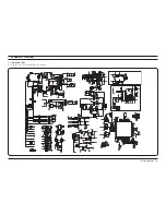
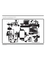
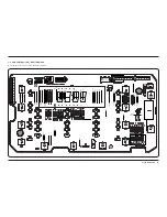
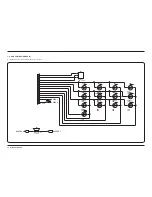
2 _ Schematic Diagram

7

-2.  SUB CONTROL (LCD) - WF520ABP/XAA, WF520ABW/XAA

►  This Document can not be used without Samsungs authorization.

WC_RESET

"!6

6

M!

!$

+15_IS

+5V_IS

+3.3V_IS

#%

6

U&

2

1

2

1

#

6

N&

+
*

7

2

2

1

)#

+)!$-&

).

/54

'.$

U&

2

1

6

#%

#

N&

6

2

1

#%

6

2

U&

1

6

N&

#

2

1

GND

GND

+

2

* 7

2

1

GND

N&

#

6

2

1

7

*

+

2

2

1

2

7

*

+

2

1

7

--"4

1

#

"

%

#

6

N&

2

1

+3.3V_IS

7

*

+

2

2

1

+3.3V_IS

7)2%?0

#.

+2#3

1

7

#

"

%

1

2.

7

/

)

'

N&

6

#

2

1

+5V_IS

7

*

+

2

2

1

GND

GND

+3.3V_IS

GND

GND

+15_IS

MT_COM7

DTC_I

SIG_B

+5V_IS

2

7
*

+

2

1

--"4

7

1

#

"

%

7

1

+2#3

#

"

%

*

+

7

2

2

1

6

U&

#%

2

1

U&

#%

6

2

1

BUZZER_1

+15_IS

+5V_IS

BUZZER_1

7

2.

1

/

)

'

1

7

2.

/

)

'

+3.3V_IS

MAIN_RESET

DRUM_LIGHT

6

N&

#

2

1

&

2

7

2

1

+15_IS

U&

6

#%

2

1

U&

6

#%

2

1

GND

3-7$7

7(4

#.

+3.3V_IS

7

+

*

2

2

1

2

*

+

7

2

1

CS
WC_BUSY
WC_SCLK
WC_RXD

WC_TXD

WC_CNVSS

WC_EPM

WC_CE

SD_OUT

+

2

*

7

2

1

GND

7)2%?0

#.

7

+

&

2

2

1

CS

WP

SD_IN

SC

HOLD

+3.3V_IS

+3.3V_IS

7

+

*

2

2

1

&

7

+

2

2

1

*

7

+

2

2

1

SD_OUT

#

6

N&

2

1

GND

GND

WC_CNVSS

)#

-3&$0'0

0?

!6##

62%&

0?

!633

0?

0?

0?

0?

0?

0?

0?

0?

0?

0?

0?

0?

0?

0?

0?

0?

0?

0?

0?

0?

0?

0?

0?

0?

0?

0?

0?

0?

0?

"94%

0?

#.633

0?

8#).

0?

8#/54

0?

2%3%4

0?

8/54

0?

633

0?

8).

0?

6##

0?

0?

633

0?

0?

0?

6##

0?

0?

0?

0?

0?

0?

0?

0?

0?

0?

0?

0?

0?

0?

0?

0?

0?

0?

0?

0?

0?

0?

0?

0?

0?

0?

0?

0?

0?

0?

0?

0?

0?

0?

0?

0?

0?

0?

0?

0?

0?

0?

7

*

2

2

1

7

-

*

2

2

1

GND

#

N&
6

2

1

+3.3V_IS

2

+* 7

2

1

JOG_B
JOG_A

BZ_PW1
BZ_PW2
BZ_FRQ

WC_RESET

6

N&

#

2

1

6

N&

#

2

1

-0

)#

.3

6##

1

.(/,$

.7

#

633

$

--

2%$

,%$

2

1

GND

DRUM_LIGHT

+3.3V_IS

GND

SC
SD_IN
LCD_CS
LCD_CD

LCD_RST

6

#

N&

2

1

LCD_W/D

LCD_W/D

6

N&

#

2

1

2

2

1

+15_IS

+2#3

7

1

#

"

%

GND

GND

LCD_LED

+3.3V_IS

2

+

*

7

2

1

*

7

2

+

2

1

#

N&
6

2

1

N&
6

#

2

1

GND

6

N&

#

2

1

 * 7

2

2

1

JOG_A

JOG_B

GND

MT_COM0
MT_COM1
MT_COM2
MT_COM3
MT_COM4
MT_COM5
MT_COM6

--

2%$

,%$

2

1

4$

0+%!

6

7

2

1

N&
6

#

2

1

6

N&

#

2

1

+3.3V_IS

GND

WC_TXD

WC_RXD

WC_SCLK

WC_BUSY

SD_IN

SD_OUT

CS

LCD_RST

WC_EPM

LCD_CS

LCD_CD

LCD_LED

SC

WC_CE

HOLD

2

+

*

7

2

1

2

2

1

2

2

1

+

2

7

*

2

1

+3.3V_IS

BUZZER_2

BZ_PW1_1

BZ_FRQ

+3.3V_IS

BZ_PW2_1

GND

GND

MT_KEY1

LED_0

MT_OP

MT_KEY2

LED_1

LED_2

LED_3

WP

MT_OP

MT_KEY2
MT_KEY1

GND

MT_COM0
MT_COM1
MT_COM2
MT_COM3
MT_COM4

* 7

2

+

2

1

#

N&
6

2

1

+

*

7

2

2

1

6

#

N&

2

1

+15_IS

2

+

*

7

2

1

+

*

7

2

2

1

37

6

M!

M!

6

37

MAIN_RELAY_WATCHDOG

MAIN_RESET

7

)#

)

/

)

/

)

/

)

/

)

/

)

/

)

/

'.$

6##

WATER_LEVEL_TO_MAIN

M_SW

WATER_Lv

6

M!

37

37

6

M!

37

6

M!

37

6

M!

DRY_AIR_T

37

6

M!

6

M!

37

37

6

M!

37

6

M!

37

6

M!

6

M!

37

LED_4
LED_3

GND

$

.73

6

M!

2

1

M!

6

.73

$

2

1

$

.73

6

M!

2

1

M!

6

.73

$

2

1

$

.73

6

M!

2

1

$

M!

6

.73

2

1

.73

6

M!

$

2

1

M!

6

.73

$

2

1

$

.73

6

M!

2

1

M!

6

.73

$

2

1

$

.73

6

M!

2

1

M!

6

.73

$

2

1

$

.73

6

M!

2

1

M!

6

.73

$

2

1

LED_2
LED_1

BZ_PW1
BZ_PW2

LED_0

GND

7(4

3-7$7

#.

BZ_PW1_1
BZ_PW2_1

-- 2%$

,%$

2

1

MT_COM5
MT_COM6

#

N&
6

2

1

2

2

1

-- 2%$

,%$

2

1

-- 2%$

,%$

2

1

-- 2%$

,%$

2

1

-- 2%$

,%$

2

1

-- 2%$

,%$

2

1

-- 2%$

,%$

2

1

-- 2%$

,%$

2

1

MT_COM7

)#

+)$!&

6##

'.$

$

.73

6

M!

2

1

GND

SIG_A
SIG_B
DTC_I

2

2

1

WATER_T

DRY_CON_T

GND

2

2

1

2

2

1

2

2

1

2

2

1

2

2

1

2

2

1

2

2

1

#

N&

6

2

1

6

N&

#

2

1

7

2

+ *

2

1

2

+ *

7

2

1

M_SW

DRY_AIR_T

DRY_CON_T

WATER_T

WATER_Lv

6

N&

#

2

1

6

N&

#

2

1

2

+ *

7

2

1

2

+ *

7

2

1

2

+ *

7

2

1

2

+

*

7

2

1

2

+

*

7

2

1

2

+

*

7

2

1

2

+

*

7

2

1

7)2%?0

#.

+3.3V_IS

!$

"!6

6 M!

+

*

7

2

2

1

2

-

*

7

2

1

#

N&
6

2

1

GND

+3.3V_IS

GND

GND

)#

4#5"&.

)

6$$

/

)

)

/

/

)

)

/

/

)

633

/

#

N&
6

2

1

1

+2#3

7

#

"

%

GND

GND

-(Z

38

8

2

1

#

N&

6

2

1

LED_4

#

N&

6

2

1

6

M!

37

+3.3V_IS

2

+

*

7

2

1

GND

6

N&

#

2

1

2

2

1

BUZZER_2

7

*

+

2

2

1

M!

6

.73

$

2

1

+15_IS

1

+2#3

7

#

"

%

GND

--

2%$

,%$

2

1

--

2%$

,%$

2

1

+3.3V_IS

$

.73

6M!

2

1

M!

6

.73

$

2

1

$

.73

6M!

2

1

M!

6

.73

$

2

1

$

.73

6M!

2

1

M!

6

.73

$

2

1

$

.73

6M!

2

1

M!

6

.73

$

2

1

$

.73

6M!

2

1

M!

6

.73

$

2

1

$

.73

6M!

2

1

M!

6

.73

$

2

1

$

.73

6M!

2

1

M!

6

.73

$

2

1

6

N&

#

2

1

2

2

1

GND

#

N&
6

2

1

6

N&

#

2

1

$"

$30

#

N&
6

2

1

%$,%$

,#$

6$$

633

3#+

3$!

#3

#$

6,#$

234

!

+

6$$

.#

7)2%?0

#.

2 + *

7

2

1

7

*

2

2

1

MAIN_RELAY_WATCHDOG

WATER_LEVEL_TO_MAIN

SIG_A

+)!!0

)#

).

/54

'.$

"5::%2?

-4?#/-

Washer : O

Dryer : X

Dryer : X

Washer : O

Dryer : X

Washer : O

Dryer : 6P

Washer : 10P

Dryer : 12V

Dryer(Elec) : D1

Washer : N.C.

Dryer(Gas) : D1-D2

Dryer : X

Washer : O

Dryer : 12V

Dryer : 12V

Washer

Dryer

R37-R40 : 470ohm

R41-R45 : 620ohm

R24 : 390ohm

R41-R45 : 330ohm

R37-R40 : 330ohm

R24 : 330ohm

R30,70 : 100ohm

Dryer

R30,70 : 470ohm

Washer

Dryer : 12V

Dryer : X

Washer : O

Dryer : 12V

Dryer : 12V

Dryer : DC07-00117B

Washer : DC07-00117A

Содержание WF511AB series

Страница 1: ...RACE PROJECT WF511AB GRACE JR PROJECT Model Code WF520ABP XAA WF520ABW XAA WF511ABR XAA Refer to the service manual in the GSPN see the rear cover for the more information 1 Safety Instructions 2 Feat...

Страница 2: ...disassembly drawings 12 4 Troubleshooting 23 4 1 Error modes 23 4 2 Corrective actions for each error code 27 5 PCB diagram 33 5 1 Main PCB 33 5 2 Connector and Relay Part Manual Main PCB 34 5 3 Sub 3...

Страница 3: ...isconnect the power plug before servicing 4 Failing to do so may result in a risk of electric shock Do not allow consumers to connect several appliances to a single power outlet at the same time 4 The...

Страница 4: ...kage AFTER SERVICING Check the wiring 4 Ensure that no wire touches a rotating part or a sharpened part of the electrical harness Check for any water leakage 4 Perform a test run for the washing machi...

Страница 5: ...ot press a control button using a sharp tool or object 4 This may result in electric shock or damage to the product WHILE SERVICING When wiring a harness make sure to seal it completely so no liquid c...

Страница 6: ...utlet and measure the insulation resistance between the power plug and the grounding wire of the washing machine The value must be greater than 10M when measured with a 500V DC Megger Check whether th...

Страница 7: ...use of Pure Cycle Deep steam The Deep Steam feature boosts cleaning performance and loosens grime and dirt thus providing superior cleaning results Diamond drum Take gentle care of your fabrics With i...

Страница 8: ...tal is available to raise the washer for easier loading and unloading It also offers a built in storage drawer that can hold a 100 oz bottle of detergent Stacking Model No SK 5A XAA Samsung washers an...

Страница 9: ...m A High Overall 38 6 981 mm B Width 27 686 mm C Depth with door open 90 51 2 1300 mm D Depth 34 1 865 mm Water pressure 20 116 psi 137 800 kpa Weight 110 kg 242 5 lb Capacity 5 0 Cu Ft iec Power cons...

Страница 10: ...T Yes Heater 900W Yes Yes Yes Diamond Drum Yes Yes Yes Washing Cycle 13 13 12 Delay Wash 24 hrs 24 hrs 24 hrs Tilted Drum 5 5 10 Sound pressure Ave 56 3 dBA Ave 56 3 dBA Ave 57 5 dBA Target Performanc...

Страница 11: ...ATER C DC97 15648A 1 Default MANUAL BOOK DC68 02838A 1 Default CAP FIXER DC67 00307A 6 Default HOSE HANGER DC62 10278A 1 Default Note You can purchase additional water supply and drain hoses from a se...

Страница 12: ...10 _ Features and Specifications MEMO...

Страница 13: ...Motor 1 Balance 5 2 holes of each left and right of the shock absorber 1 Pulley hole Open End wrench 10mm 13mm 19mm Replaceable for the box driver Since the bolt runs idle when the box driver is used...

Страница 14: ...removing the rotor requires a lot of strength due to the magnetic force of the Rotor and it may come off suddenly your hand or arm may be injured by the edge of the Stator or Frame Therefore take prec...

Страница 15: ...s and remove the 4 screws on the PANEL CONTROL Water valve Noise filter Main PCB Sensor pressure 3 With the top cover removed you will now have access to service the Water pressure sensor EMI Noise Fi...

Страница 16: ...nel Control Check Main PCB and Sub PCB 6 Pull the PANEL CONTROL towards and then lift it upwards to separate 7 Carefully disconnect the three wiring connectors by hand 8 Remove the 11 screws holding t...

Страница 17: ...Remove the 2 screws holding GUIDE PCB M at BRACKET SPRING R 2 Lift up ASSY PCB M 3 Move the ASSY PCB M at parallel direction 4 Separate 2 hooks 5 After SVC Certainly check the 2 hooks assembled correc...

Страница 18: ...VER DOOR including the 3 arrow screws holding the HINGE DOOR 4 Putting and pressing hard a flat head screwdriver into the furrow between COVER DOOR and SUPPORT HINGE 5 Making a semicircle with screwdr...

Страница 19: ...g along the circle 2 Remove the 2 screws to separate the DOOR LOCK S W 3 Remove the 4 screws at the top of FRAME FRONT 4 Push the lever and pull it towards to open the COVER FILTER 5 Separate the rema...

Страница 20: ...to the valves Use the plier to remove the hose Disassembling and Repairing the Water Level Sensor 1 Separate the wire connected the SENSOR PRESSURE 2 Adjust the plastic clip of pressure sensor between...

Страница 21: ...e connected to the PUMP and then pull the HOSE AIR 4 Separate the Clamp of the hose connected to the PUMP and then pull the HOSE DRAIN 5 Separate the wire connected to the PUMP Removing the Remaining...

Страница 22: ...FRAME PLATE U 2 Remove the 3 bolts fixing WEIGHT BALANCER and then pull it towards with caution 3 Remove the 4 bolts fixing DAMPER to take ASSY TUB out 4 Remove all wire and hose connected the ASSY T...

Страница 23: ...te the TUB FRONT and TUB BACK Disassembling the DRUM 1 Separate the ASSY DRUM from TUB remove 6 M10 bolts from the upper ASSY DRUM disassemble the ASSY FLANGE SHAFT 2 Remove 12 screws from the outer s...

Страница 24: ...nch manually without using pincers or tweezers When you re assembly the heater make sure to install the Heater exactly onto the Bracket inside the Tub If it is not properly installed it may cause a fi...

Страница 25: ...oo much laundry etc bE This occurs due to erroneous operating signals from the motor hall sensor The IPM terminal of the main PBA is not connected The DD motor cover is out of place The PCB housing te...

Страница 26: ...ck or is being pressed continuouly ERROR The Power button is pressed continually for more than 12 seconds A switch is jammed or stuck due to be pressed unevenly due to deformation of the control panel...

Страница 27: ...of too much detergent Water leakage occurs because the connecting hose to the detergent drawer is connected incorrectly The drain pump filter cover is engaged incorrectly Water leakage occurs at the d...

Страница 28: ...inished the normal cycle proceeds Sud or SUdS is displayed when too much foaming is detected and End is displayed when the removal of the foaming is finished This is one of the normal operations It is...

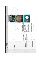
Страница 29: ...and the connector are connected Checking Part Pink Color Wire Oragne Color Wire Frequency Approx 26 4 KHz with no load Washing Motor Error and Hall Sensor Error 3E E3 bE The Motor is not working prop...

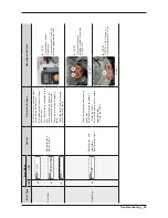
Страница 30: ...ng ERROR Freezing in the winter season Foreign materials in the drain pump Poor physical connection Drain pump fault Main PCB fault If the drain pump revolutions are restrained due to freezing in the...

Страница 31: ...or sensing circuit Replace if faulty TYPE 1 Check the door switch Resistance The resistance of 1 and 3 Pin Must be approximately 125 dL ERROR The Door was unlocked wh ile the washer was running LO The...

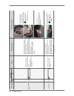
Страница 32: ...ce if it does not operate normally DRAIN PUMP TYPE Automatic Drainage Check whether there is any foreign material in the bellows Check for any foreign material such as underwear wires or coins PUMP TY...

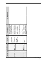
Страница 33: ...ional error replace it A tE error occurs Check the connections for the dry heater temperature sensor connector If the dry heater temperature sensor has a functional error replace it Check the connecti...

Страница 34: ...32 _ Troubleshooting MEMO...

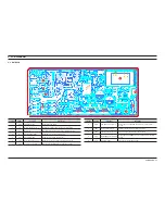
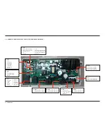
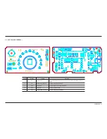
Страница 35: ...ply the 3 phase drive voltage for the Washing Motor 7 CN3 Hole Sensor Connection Port Detect whether the Washing Motor is working normally Location Part No Function Description 8 CN10 SUB PBA Connecti...

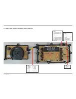
Страница 36: ...n Sensor LOCK UNLOCK 3 Empty Pin CN7 1 Reactor Connection Port 2 Reactor Connection Port RY13 1 Steam Heater Relay Switch 2 Steam Heater Relay Switch RY13 1 Washing Heater Relay Switch 2 Washing Heate...

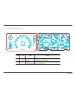
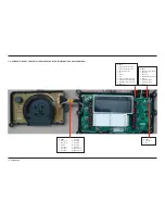
Страница 37: ...coder is operated the menu is closed 2 CN7 MAIN PBA Connection Port For communications with main PBA 3 CN6 Sensor input Sensing the water level and water temperature 4 CN2 Drum Light Turn on when door...

Страница 38: ...signal 11 Led signal 12 Buzzer signal 13 Buzzer signal CN2 1 Drum light 2 15V CN10 1 Communications Port Rx 2 Communications Port Tx 3 Reset Signal ouput 4 5V 5 Ground 6 15V 7 Main reset signal from...

Страница 39: ...ssed or the encoder is operated the menu is closed 2 CN7 MAIN PBA Connection Port For communications with main PBA 3 CN6 Sensor input Sensing the water level and water temperature 4 CN2 Drum Light Tur...

Страница 40: ...l 11 Led signal 12 Buzzer signal 13 Buzzer signal CN3 1 Drum light 2 15V CN6 1 Communications Port Rx 2 Communications Port Tx 3 Reset Signal ouput 4 5V 5 Ground 6 15V 7 Main reset signal from SUB 8 W...

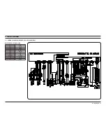
Страница 41: ..._ 39 6 WIRING DIAGRAM 6 1 WIRING DIAGRAM WF520ABP XAA WF520ABW XAA Reference Information BLK BLACK BLU BLUE GRN GREEN GRY GRAY NTR NATURAL ORG ORANGE PNK PINK RED RED SKYBLU SKYBLUE VIO VIOLET WHT WH...

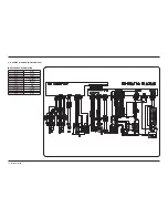
Страница 42: ...40 _ Wiring Diagram 6 2 WIRING DIAGRAM WF511ABR XAA Reference Information BLK BLACK BLU BLUE GRN GREEN GRY GRAY NTR NATURAL ORG ORANGE PNK PINK RED RED SKYBLU SKYBLUE VIO VIOLET WHT WHITE YEL YELLOW...

Страница 43: ...7 OHM 2 2 1 N 6 2 1 7 2 2 1 U 6 2 1 3 6 2 1 U 6 2 1 N 6 2 1 73 6 M 2 1 2 7 2 1 2 7 2 1 2 7 2 1 73 6 M 2 1 2 7 2 1 2 7 2 1 2 7 2 1 73 6 M 2 1 2 7 2 1 7 2 2 1 2 7 2 1 2 7 2 1 2 7 2 1 73 U 6 2 1 UPD70F3...

Страница 44: ...1 LED_0 MT_OP MT_KEY2 LED_1 LED_2 LED_3 WP MT_OP MT_KEY2 MT_KEY1 GND MT_COM0 MT_COM1 MT_COM2 MT_COM3 MT_COM4 7 2 2 1 N 6 2 1 7 2 2 1 6 N 2 1 15_IS 2 7 2 1 7 2 2 1 37 6 M M 6 37 MAIN_RELAY_WATCHDOG MAI...

Страница 45: ...W U W X X Y W W W T Y X _ Z U Y X X Y W W W T Y X _ Z U X X Y W W W T Y X _ Z W U X X Y W W W T Y X _ Z W U W X X Y W W W T Y X _ Z W U W X X Y W W W T Y X _ Z W U X X Y W W W T Y X _ Z U Y X X Y W W...

Страница 46: ...M 6 3 37 2 2 1 2 2 1 2 2 1 2 2 1 2 2 1 2 2 1 2 2 1 2 2 1 2 2 1 2 2 1 2 2 1 2 2 1 2 2 1 Z 03 0 2 1 BUZZER_1 BUZZER_2 BUZZER_1 BUZZER_2 7 4 3 7 7 7 4 Sub Graphic This Document can not be used without S...

Страница 47: ...rope samsungportal com China http china samsungportal com Asia http asia samsungportal com Mideast Africa http mea samsungportal com This Service Manual is a property of Samsung Electronics Co Ltd Any...

Отзывы: