Removal and Reassembly _ 17
Part
Figure
Description
DD Motor
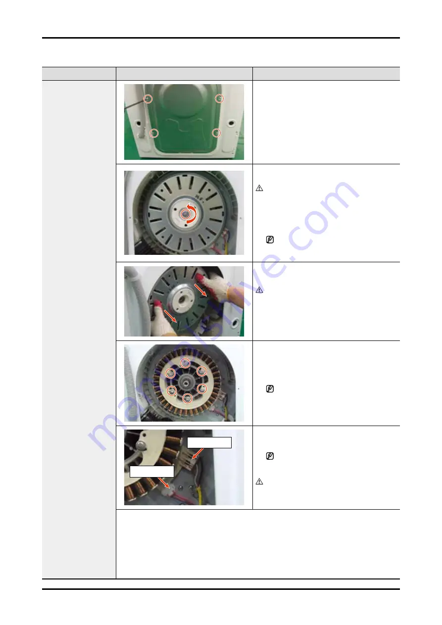
1. Unfasten the 4 screws that hold the back
cover in place. Remove the back cover by
sliding it down.
(When assembling, slide the back cover
up.)
2. After removing the back cover, unfasten the
M19 nut that holds the motor in place.
Caution
Turn the nut counterclockwise to unfasten
it. You have to turn it with a quick ‘twist’
because turning it slowly turns the motor
at the same time and makes it difficult to
loosen the nut.
Do not try to unfasten the nut by
inserting a screw driver into the motor.
This may cause a motor malfunction.
3. Remove the M19 nut washer and then
remove the rotor.
Caution
Pulling out the rotor requires some force
and is pulled out suddenly rather than
slowly. Be careful, as the stator when pulled
out, may cause damage to the corners of
the frame, or injury to your hands or arms.
4. Unfasten the six (6) M10 screws. →
Remove the assy bracket motor. →
Remove the stator.
When unfastening the last one of the six
(6) screws, hold the stator by hand to
prevent it from falling due to its weight.
Hall sensor
Motor wire
5. Remove the motor wire and hall sensor while
holding down the navel of the housing.
To remove the connector, press the
navel of the housing and pull it towards
the inside.
Caution
Be cautious when handling as the hall
sensor is susceptible to shock.
4
Check Points for Troubleshooting
1. Check whether there are any foreign substances between the rotor and the stator.
2. Check whether the motor power wires (blue, while, red) are connected correctly.
3. Check whether the hall sensor wire is connected correctly.
- Connect the motor power wires in the order blue, white and red, starting from the
furthest right. Check whether each resistance between blue and white, white and red,
red and blue is 15Ω.


