10 _ Disassembly and Reassembly
3-2. STANDARD DISASSEMBLY DRAWINGS
► This is a standard disassembly diagram and may differ from the actual product.
Use this material as a reference when disassembling and reassembling the product.
Part
Figure
Description
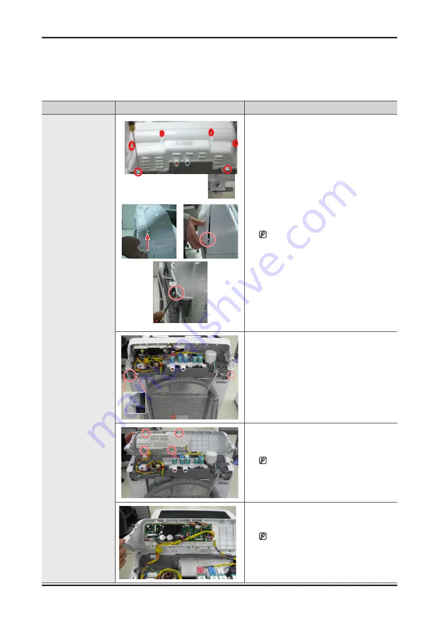
Sub and Main PCB
Assembly
1. Remove the 6 screws holding the control
panel assembly.
2. Separate the both hooks. (Left and Right)
3. Separate the cover panel upward.
If it is difficult to disassemble, use the (-)
driver to disassemble hooks.
(Be careful damage of hooks.)
4. Remove the 2 screws holding the control
panel assembly and turn the panel over.
5. Pull the Encoder-Knob to separate it and
then remove the 4 fixing screws.
When reassembling the PCB, take care
that you do not damage the control-panel
fixing hook. After replacing the sub PCB,
check the key operation.
6. Separate the cover pcb(m) and the wires
connected to the main PBA.
After reassembling the housing, check
if the wires are properly connected.
When disassembling and reassembling
the housing, take care that you do not
damage the part.


