Samsung VRR P10 Скачать руководство пользователя страница 6

6

/

50

Temperature and humidity range:

Working temperature and humidity
range

-30 ~ 50

/ 10% ~ 90%

Storage temperature and humidity
range

-30 ~ 60

/ 10% ~ 95%

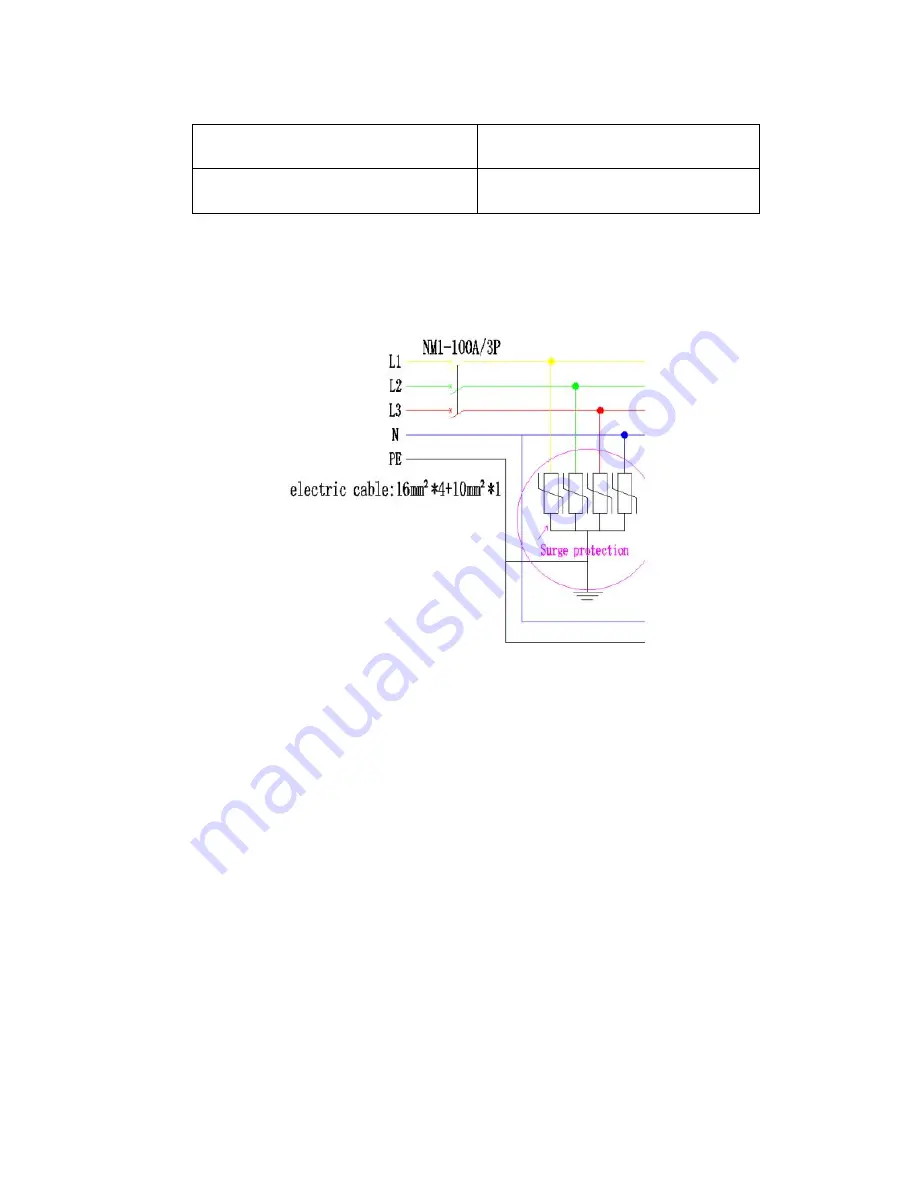
Each main power cable can carry a maximum current of 16A. Note that the total

current of the cabinets cascaded in one main power cable should not exceed
16A. Refer to Table 7-1 for the specific quantity.

Surge protection device of power should be added in the power distributor.

After the display is idle for a period of time, please turn on the power and input the

signal for the first time, and adjust the brightness of the display to the lowest level
for about half an hour and gradually increase the brightness gradually, then use it
normally.

Please provide a good ventilation environment for the display to facilitate the heat

dissipation of the display; and keep away from flammable and explosive
materials.

Since the display LED lamps of the VRR P10 are relatively fragile, do not collide

the surface with hard and sharp objects to prevent damage to the lamp body.

Hot swapping is not allowed. Damage to the connector pins caused by hot

swapping is not covered by the warranty.

2.4 Instructions for Use

Do not place the VRR P10 in an environment where moisture, dust, corrosion,
extreme cold and heat (exceeding the temperature of the parts), as this
environment can cause LED damage or discoloration on the module.

Содержание VRR P10

Страница 1: ...1 50 Product Manual VRR P10 ...

Страница 2: ...isplaying System Connection Diagram 9 Chapter 5 VRR P10 Installation 10 5 1 Rotary Single Leg Introduction 10 5 2 Cabinets Alignment 11 Chapter 6 VRR P10 Installation Process 12 6 1 Power Cable Connection 12 6 2 Signal Cable Connection 13 Chapter 7 VRR P10 Displaying Controller Set up Steps 14 7 1 Nova Lct Mars Control System Instruction 14 Appendix A Dimensional Drawing of Main Components 18 Appe...

Страница 3: ...gh gray level high brightness three high features and dual backup of power and signal And with a professional digital stadium solution unique tilt angle adjustable the exclusive opening of the stadium LED display intelligent new era The front and rear maintenance of the module is quick and easy with a uniquely designed anti collision beam and emergency access to protect the safety of the players T...

Страница 4: ...ow all safety guidelines safety instructions warnings and precautions in this manual Warning Pay attention to the hanging load of the flykits Warning When installing the cabinet wear a helmet to avoid the risk of personal injury Warning Pay attention to your fingers when installing the cabinets For Installer The display installer must be a trained qualified and experienced technician Security tips...

Страница 5: ...hey are non abrasive non corrosive non marking materials or reagents To prevent the risk of electric shock ensure that the cabinet is properly grounded when it is installed When performing the screen hanging screen the operator should wear anti static equipment and the operation should be careful and careful to prevent the cabinet from falling After the screen installation and connection is comple...

Страница 6: ...the lowest level for about half an hour and gradually increase the brightness gradually then use it normally Please provide a good ventilation environment for the display to facilitate the heat dissipation of the display and keep away from flammable and explosive materials Since the display LED lamps of the VRR P10 are relatively fragile do not collide the surface with hard and sharp objects to pr...

Страница 7: ...signal cables between the cabinets are not allowed to be hang with anything VRR P10 modules should not be used near any device other than CE and UL ETL certified The VRR P10 is an outdoor product Do not install or use it in an outdoor environment Keep the product in a dry environment and avoid direct sunlight When reconnecting the power and signal cables ensure that the cables are connected accord...

Страница 8: ...urge protection switch Each power output interface has a circuit breaker The maximum current of the interface is 20A and its total power consumption shall be over 1 5 times the total power consumption of the display Grounding requirements All parts of the power distribution system must be grounded to prevent static electricity from harming the human body and causing damage to the electronic compon...

Страница 9: ...he sending box 4 Computer based on the windows system computer set the Sending box parameters play the program 5 Power cord power supply to the display 6 Signal cable transmission of video data processed by the sending box 7 Backup signal cable backup function not required replace the function of 6 when there is an abnormality in 6 8 LED Cabinet LED display unit as shown in Picture 4 1 there are 2...

Страница 10: ...chapter mainly introduces the installation process of VRR P10 HD products and guides customers to install the products correctly 5 1 Rotary Single Leg Introduction A Single leg and Cabinet 0 Degree B Single leg and Cabinet Rotating to 90 Degree ...

Страница 11: ...11 50 C Single leg and Cabinet 90 Degree 5 2 Cabinets Alignment Align the two cabinets horizontally and lock the two latches with a hex driver to complete the splicing ...

Страница 12: ...s has a wire size of 3 2 5mm2 one for the parent aviation head and one for the male aviation head 6 1 3 Main Power Cable Connect the power cable between the cabinet and the power distribution cabinet The cable size is 3 2 5mm2 One end is connected to the power input port of the cabinet and the other end is connected to the power distribution cabinet The maximum current of the aviation head used on...

Страница 13: ...he box and the display screen to transmit video data with a length of less than 70m Remarks When the transmission distance is greater than 70m it is possible to transmit data by optical fiber and the longest distance is 20 kilometers Signal cascading line used for signal transmission between cabinets 6 2 3 Cabinet Signal Cable Connection 1 During the installation process pay attention to the prote...

Страница 14: ...x is limited and the actual project should refer to the corresponding signal connection Drawing connections Chapter 7 VRR P10 Displaying Controller Set up Steps This chapter mainly introduces the setup steps of the VRR P10 product control software 7 1 Nova LCT Mars Control System Instruction 7 1 1 Load display profile Double click to open the NovaLCT Mars software as shown in Picture 7 1 click Use...

Страница 15: ... 2 Click the Confirm button on the Screen Config interface as shown in Picture 7 2 Picture 7 2 Click the load files button on the Scan Board interface load the rcfgx file corresponding to the display and then click the Send to Receiving card button After the display shows normal click Save as shown in Picture 8 12 Picture 8 13 Picture 7 3 ...

Страница 16: ...file If the parameters are inadvertently modified the display screen will not display properly The configuration file needs to be reloaded and sent to the receiving card After sending and saving the configuration file the display should display the same content in units of the cabinet To load the screen file ...

Страница 17: ...s load the scr file If the parameters are inadvertently modified the display screen is not displayed properly The screen file needs to be reloaded and sent to the receiving card At this point the entire screen connection parameter setting has been completed At this time the entire screen should be displayed on the desktop of the computer Next you can play the program you want in the initial interf...

Страница 18: ...18 50 Appendix A Dimensional Drawing of Main Components A 1 VRR P10 Cabinet Size A 2 Dolly 5 in 1 ...

Страница 19: ...19 50 A 3 Flight Case 2 in 1 ...

Страница 20: ...00 pixels m2 12 288 pixels panel LED Module Dimensions 320 320 mm Panel Dimensions W H D 1 280 960 153 mm Stand Dimensions W H D 655 x 110 x 36 mm No of Modules Per Panel W H 4 x 3 Physical Resolution of Module W H 32 32 Physical Resolution of Panel W H 128 96 Set Weight With Stand 62 3 5 kg panel 50 5 3 kg m2 Without Stand 59 4 3 5 kg panel 48 3 3 kg m2 Stand Weight 2 6 kg pcs Cabinet Material Al...

Страница 21: ...on Contrast Ratio 4 000 1 Electrical Environmental Average Power Consumption 176 W m2 Max Power Consumption 586 W m2 Max Daisy Chain Signal 46 575 000pixels 52 cabinets 650 000pixels Power 5 cabinets 220v 2 cabinets 110v Operating Temp Humidity 30 50 C 10 90 Storage Temp Humidity 30 60 C 10 95 Expected LED Lifetime Max 100 000 Hrs Certification Certification CE EAC ETL FCC KCC UL CB CCC Class A Po...

Страница 22: ...MRV410 3 Power supply AP196A 115309258006R Power AP196A 4 HUB board L 204100000039B HUB board L 5 HUB board R 204100000040B HUB board R 6 Power signal cable A 0 38m 214030000029R Power signal cable A 0 38m 7 Power signal cable B 0 45m 214030000030R Power signal cable B 0 45m 8 Power signal cable C 0 65m 214030000031R Power signal cable C 0 65m ...

Страница 23: ...oor 12 Main power cable 10M SEETRONIC outdoor European regulations 208030100103R Main power cable 10M SEETRONIC outdoor European regulations 13 Main signal cable 30M SEETRONIC outdoor 209010200054R Main signal cable 30M SEETRONIC outdoor 14 Mask 160 7x160 7x3 5MM 120200206030R Mask 160 7x160 7x3 5MM 15 LED light Nationstar SMD3535 110000206005R LED lights Nationstar SMD3535 16 Driver IC Chipone IC...

Страница 24: ...iation female head SAC3FX 120500207012R Power aviation female head SAC3FX 21 Power aviation male head SAC3MX 120500207013R Power aviation male head SAC3MX 22 Signal aviation head SE8MC 05 120500407026R Signal aviation head SE8MC 05 23 Sender box 210020000004R MCTRL660 Standard 24 Hexagonal wrench 120600304014R Hexagonal wrench ...

Страница 25: ...50 Appendix C Tools to be prepared C 1 Adjustable Wrench conventional C 2 Screwdriver medium size C 3 Allen key M3 is used to open the power cabinet M8 is used to fix the connecting piece C 4 Rotating key ...

Страница 26: ...hown in Figure D 1 below Picture 1 2 Check if the DVI cable the signal cable are in good contact or not As shown in Picture 2 below 3 Check at the same time if the green lights of the sending card and the receiving card are blinking or not As shown in Picture 2 below Picture 2 4 Check for copy mode As shown in Picture 3 Picture 3 ...

Страница 27: ...in Picture 4 Picture 4 2 A string of lamps are not lit or constantly lit one of the 16 bit pins of the constant current IC is damaged or in pseudo soldering As shown in Picture 5 Picture 5 3 If lamps in a unit IC control is not illuminated the IC or the current resistance may be damaged As shown in Picture 6 Picture 6 ...

Страница 28: ...he socket of the module may be too loose to be powered As shown in Picture 7 Picture 7 5 If one or several lines of the module are not lit the tube may be damaged 6 If the module shows a lack of color it may be 245 soldered or damaged ...

Страница 29: ...ods 1 1 Removal of the front maintenance module A Insert the front maintenance tool into the front maintenance maintenance mounting hole of the four modules as shown in the figure see Figure E 1 below and then rotate it 90 to the right See Figure E 2 Pic E 1 ...

Страница 30: ...c is as follows first insert the module front maintenance tool into the rotary lock cylinder in the module as shown below Pic E 4 then rotate the front maintenance tool 90 to the right jam the rotary lock cylinder and then pull the maintenance tool out you can pull out the module ...

Страница 31: ...ert the M3 Allen key into the four rear maintenance tool holes on the back of the module and rotate it 90 to the right See Pic E 6 Pic E 6 B Push out the module forward press and hold the PG head to the left and then pull it back to remove the module See step Pic E 7 ...

Страница 32: ... E 7 1 3 Dis assembly of the power supply box A Remove the power box first loosen the lock under the power box see Pic E 8 Pic E 8 B Lift the power supply box up and remove it later to remove the power supply box See Pic E 9 steps ...

Страница 33: ...33 50 Step Pic from left to right E 9 ...

Страница 34: ...he screws on the cover See Pic E 10 Pic E 10 B First remove the receiving card cable and the current sharing cable and remove the power cable See Pic E 11 Pic E 11 C Remove the network cable first then remove the cable above the receiving card and remove the 4 screws on the receiving card to remove the receiving card in parallel See Pic E 12 for steps ...

Страница 35: ...35 50 Pic E 12 ...

Страница 36: ...36 50 The second step is to repair the power supply C Remove the four screws on the power back plane See Pic E 13 Pic E 13 D Remove the line above the power supply see step Pic E 14 ...

Страница 37: ...t connection board maintenance A first remove the 2 9 air socket fixing nut on the power box with a wrench see step Pic E 15 1 First loosen the fixing nut 2 Remove the retaining ring 3 Remove the connecting plate 4 Pull out the cable ...

Страница 38: ...38 50 5 Remove the screws that secure the wire Pic E 15 1 6 LCD panel maintenance A first remove the cable and screws next to it see step Pic E 16 First remove the network cable Remove the fixed screws ...

Страница 39: ...directly and remove the internal screws Direct replacement Pic E 16 1 7 Empty open box internal maintenance the same way as the power supply box is removed from the cabinet A first remove the screws on the empty box see Pic E 17 ...

Страница 40: ...ance first remove the screws for fixing on the empty open box see Pic E 18 Pic E 18 C First remove the screws at both ends of the upper cover of the leakage switch and then remove the screws that fix the wire on the switch See step Pic E 19 ...

Страница 41: ...0 Pic E 19 For D terminal block maintenance first remove the screws that fix the cover and then remove the screws on the fixed and empty open boxes Finally remove the wire screws See step Pic E 20 Pic E 20 ...

Страница 42: ...sters of the trailer to fix the trailer 2 b Remove the upper cover of the trailer by supporting the upper snap lock both on both sides see Pic F 2 2 c Then support the lower snap lock on both sides both sides see Pic F 3 tilt the left and right supports one forward one backward remove the left and right supports see Pic F 4 F 5 the left and right supports are connected to the base by hinges detach...

Страница 43: ...43 50 Pic F 2 Pic F 3 ...

Страница 44: ...ic F 5 Pic F 6 Left and right support frame and base hinge joint 3 Install the stadium screen cabinet into the trailer 3 a Rotate the bottom of the stadium screen by 90 to receive the bottom of the cabinet see Pic F 7 ...

Страница 45: ...8 Lift the cabinet into the middle of the trailer through the handles on both sides of the cabinet and locate the positioning hole and trailer of the cabinet Pin put on the trailer see Pic F 9 3 c Repeat the steps of 3 b and put the cabinet into the trailer from the middle to the sides Pic F 7 ...

Страница 46: ...46 50 Pic F 8 Front Lamp Surface Trailer silk screen Cabinet Location Hole Dolly Location Pin ...

Страница 47: ...ight supports in the direction to make the hinge holes fit tightly see Pic F 11 4 b Fix the left and right sides of the support on the base see Pic F 12 rotate the left and right sides of the support in the direction of the hinge and fix the left and right supports on the base through the buckle lock see Pic F 13 4 c Locking state see Pic F 14 Pic F 10 Pic F 11 ...

Страница 48: ...ection of the upper cover silk screen should be consistent with the direction on the trailer see Pic F 15 5 b Align the positioning pin of the upper cover with the positioning hole on the left and right supports see Pic F 16 5 c Lock the four snap locks of the upper cover see Pic F 16 ...

Страница 49: ... F 15 Pic F 16 6 After pushing the trailer to the destination and stepping on the diagonal brake you can move smoothly If you want the tow wheel to rotate you can step on Direction Indicator Direction Indicator ...

Страница 50: ...50 50 the other side of the brake see Pic F 17 Pic F 17 ...

Отзывы: