


3
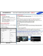
2011 LED TV Test Patterns
TROUBLESHOOTING VIDEO PROBLEMS
1.
Verify Video Operation
a)
Customer Picture Test (models available)
b)
“On Screen Display” (If OSD ok, source is
suspected)
c)
Substitute with known good Source (external DVD
or Signal Generator)
2.
Use Test Patterns in Service Mode
a)
Select an active source signal (HDMI preferred).
Test Pattern may rely on signal source to appear.
b)
Using customer remote: Mute+1+8+2+Power
c)
Using factory remote: Info+ Factory
1.
Select an active source signal (HDMI preferred).
Test Pattern may rely on signal source to appear.
2.
Access Service Mode
3.
Access
SVC
4.
Access
Test Patterns
5.
Access
Genoa-P
(located on Main PCB)
6.
Check Test Patterns
7.
If OK, suspect input Source
8.
Access
Napoli
(located on T-CON Board)
9.
Check Test Patterns
10. If OK and Genoa-P was not good, suspect Main
Board or LVDS Cable
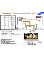
UN65D8000XFXZA
Fast Track Troubleshooting Manual Rev –
8/30/11
ON SCREEN FAILURE EXAMPLES:
Green lines or a green screen likely caused
by a defective main board, LVDS, or T-CON
If Picture & Display errors, its likely a defective
Main Board, LVDS, or T-CON
Pixelization can be caused by the
main board, but is more
commonly a source error
Vertical or Horizontal Lines are likely a
defective panel, but also T-CON, LVDS, or
Main Board. Use Test Patterns in Factory
Service Mode to determine error location


