background image

TABLE OF CONTENTS 

XII


© SAMSUNG Electronics Co., Ltd.


CHAPTER 2.


Pre-Installation Requirements 

2-1


Safety Recommendations ........................................................................................... 2-1


Cover Panels ......................................................................................................... 2-2


Best Practices-Safety............................................................................................. 2-2


General Maintenance Guidelines............................................................................ 2-2


General Site Requirements ......................................................................................... 2-3


Site Preparation ..................................................................................................... 2-3


Environment .......................................................................................................... 2-3


Inspecting the Ubigate iBG1000.................................................................................. 2-4


Required Tools and Materials ..................................................................................... 2-5


Tools...................................................................................................................... 2-5


Cables................................................................................................................... 2-5


Materials................................................................................................................ 2-5


CHAPTER 3.


Ubigate iBG1000 Installation 

3-1


Installing the Ubigate iBG1000.................................................................................... 3-1


Installing on a tabletop............................................................................................ 3-1


Installing on a Wall ................................................................................................. 3-2


Port Numbering........................................................................................................... 3-5


iBG1000 Port Numbering ....................................................................................... 3-6


Connecting the Ubigate iBG1000................................................................................ 3-7


LAN Interface......................................................................................................... 3-7


T1/E1 Interface ...................................................................................................... 3-8


Console Interface................................................................................................... 3-9


Auxiliary Interface (for Remote Access)................................................................. 3-10


Powering Up the Ubigate iBG1000............................................................................ 3-12


Connecting Power................................................................................................ 3-12


Applying Power.................................................................................................... 3-13


ANNEX A.


Specifications 

A-1


Ubigate iBG1000 Product Specifications................................................................... A-1


Interface...................................................................................................................... A-2


E1 WAN Interface ..................................................................................................A-2


T1 WAN Interface...................................................................................................A-2


Содержание Ubigate iBG1000

Страница 1: ......

Страница 2: ...ompany and product names may be trademarks of the respective companies with which they are associated This manual should be read before the installation and operation and the operator should correctly...

Страница 3: ...equency energy and if not installed and used in accordance with the instruction manual may cause harmful interference to radio communications Operation of this equipment in a residential area is likel...

Страница 4: ...phone cord and modular plug is provided with this product It is designed to be connected to a compatible modular jack that is also compliant See installation instructions for details FCC Part 68 This...

Страница 5: ...icians may replace modular parts of a system to repair or diagnose trouble Defective modular parts can be returned to SAMSUNG ELECTRONICS CO LTD for repair GENERAL Connection to party line service is...

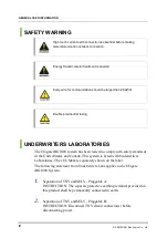
Страница 6: ...ystem has been tested to comply with safety standards in the United States and Canada This system is listed with Underwriters Laboratories The cUL Mark is separately shown on the label The following s...

Страница 7: ...hall be in compliance with the appropriate rules for terminating bonding jumpers in Part K of Article 250 of the National Electrical Code ANSI NFPA 70 and Article 10 of Part 1 of the Canadian Electric...

Страница 8: ...echanical loading D Circuit Overloading Consideration should be given to the connection of the equipment to the supply circuit and the effect that overloading of the circuits might have on overcurrent...

Страница 9: ...lation interconnection and troubleshooting descriptions Document Content and Organization This manual is composed of three Chapters and two Annexes CHAPTER 1 Ubigate iBG1000 Overview Describes Ubigate...

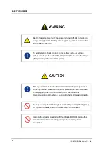
Страница 10: ...uctions that the reader should follow in order to avoid personal injury or fatality CAUTION Provides information or instructions that the reader should follow in order to avoid a service failure or da...

Страница 11: ...Concerns section is to ensure the safety of users and prevent property damage Please read this document carefully for proper use Symbols Caution Indication of a general caution Restriction Indication...

Страница 12: ...ports Caution This equipment must be installed and maintained by properly trained service personnel Make sure the proper electrical service is available before plugging this unit in and turning it on...

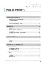
Страница 13: ...ION VII Purpose VII Document Content and Organization VII Conventions VIII Information for Product and Technical Support VIII Revision History VIII SAFETY CONCERNS IX Symbols IX Warning X Caution X CH...

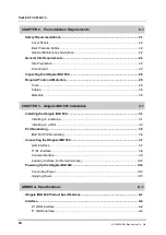
Страница 14: ...ables 2 5 Materials 2 5 CHAPTER 3 Ubigate iBG1000 Installation 3 1 Installing the Ubigate iBG1000 3 1 Installing on a tabletop 3 1 Installing on a Wall 3 2 Port Numbering 3 5 iBG1000 Port Numbering 3...

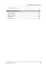
Страница 15: ...iBG1000 Installation Manual Ed 02 SAMSUNG Electronics Co Ltd XIII Ethernet LAN Interface A 3 ANNEX B Cable Specifications B 1 Console Port Cable B 1 Auxiliary Port Cable B 2 Ethernet Cable B 3 T1 E1 C...

Страница 16: ...2 Insert plastic anchors 3 3 Figure 3 3 Tightening screws 3 3 Figure 3 4 Fixing on a wall 3 4 Figure 3 5 iBG1000 Port Numbering 3 6 Figure 3 6 Connecting LAN Cables 3 7 Figure 3 7 Connecting T1 E1 Cab...

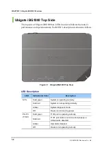
Страница 17: ...of the Ubigate iBG1000 This chapter provides an overview of Ubigate iBG1000 including information about chassis components and hardware characteristics Ubigate iBG1000 Chassis This section describes...

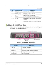
Страница 18: ...ate iBG1000 Top View LED Description LED Indication Color Description Solid green System is operating normally Solid red System is not operating normally Amber System diagnostic mode SYS Off Router is...

Страница 19: ...cted Power Off Power supply not present or power supply failure Ubigate iBG1000 Rear Side Ubigate iBG1000 rear side has four T1 E1 ports two Fast Ethernet UTP ports one auxiliary port and one console...

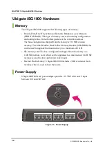
Страница 20: ...d from the factory is 512 MB of main memory The Small Outline Dual In line Memory Module SODIMM slot can be used to upgrade the main memory to a maximum of 1 GB SD memory card The base configuration s...

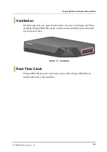
Страница 21: ...ere are grids of holes where air comes in and goes out When installing Ubigate iBG1000 ensure to make room around the system in order not to block air flow Figure 1 4 Ventilation Real Time Clock Ubiga...

Страница 22: ...CHAPTER 1 Ubigate iBG1000 Overview 1 6 SAMSUNG Electronics Co Ltd This page is intentionally left blank...

Страница 23: ...procedure that can harm you if not done correctly Electric hazard exists Verify the power is turned off Do not work on energized equipment Working on energized equipment can result in serious electri...

Страница 24: ...ectromagnetic interference EMI that might disrupt other equipment Best Practices Safety Practice these techniques to prevent accidents or injury at the installation site Make sure that the site is saf...

Страница 25: ...materials required for installation Environment Site location is important for the proper operation of Ubigate iBG1000 Place the unit in a clean and dry environment with adequate air circulation Allow...

Страница 26: ...will need to repack the unit Check the packing slip and contents of the shipping carton to ensure that you have received the following Ubigate iBG1000 body Console cable DB 9 to RJ 45 cable adapter AC...

Страница 27: ...ls The following tools are required to install these routers Electric drill Phillips screwdriver Hammer Cables The following cables may be required for operation of these routers in your environment T...

Страница 28: ...CHAPTER 2 Pre Installation Requirements 2 6 SAMSUNG Electronics Co Ltd This page is intentionally left blank...

Страница 29: ...e Ubigate iBG1000 for operation either as a tabletop or a wall mounted unit Installing on a tabletop Allow sufficient room at the front rear and side of the unit for interface cabling power cord clear...

Страница 30: ...gate iBG1000 on a wall 1 Mark two holes horizontally or vertically on a desired wall The hole distance is about 130 mm 2 Make holes on the marked position with an electric drill Make the depths and th...

Страница 31: ...cs Co Ltd 3 3 3 With a hammer insert plastic anchors into the holes Figure 3 2 Insert plastic anchors 4 Insert screws to each hole and tighten the screws with a Phillips screwdriver Be sure to remain...

Страница 32: ...CHAPTER 3 Ubigate iBG1000 Installation 3 4 SAMSUNG Electronics Co Ltd 5 Align the screws to the bottom holes of Ubigate iBG1000 and fix it Figure 3 4 Fixing on a wall...

Страница 33: ...to left starting with the next slot number based on the lower rows last left most numbered slot The main board is considered as network module slot 0 Mini modules are numbered from right to left start...

Страница 34: ...k module slot 0 does have any pluggable module unlike the others all the ports are numbered in 0 x format Therefore the Fast Ethernet ports are numbered 0 0 and 0 1 starting from right to left Likewis...

Страница 35: ...k facility environment LAN Interface The Ubigate iBG1000 accommodates several network connections Use a Category 5 minimum Ethernet cable with RJ 45 connectors to connect to the network 1 Insert the R...

Страница 36: ...ions Use a cable with RJ 45 connectors to connect to the T1 E1 network 1 Insert the RJ 45 connector on one end of the cable in any of the T1 E1 ports Figure 3 7 Connecting T1 E1 Cables 2 Connect the R...

Страница 37: ...to a PC running terminal emulation software your Ubigate iBG1000 is provided with an RJ 45 to DB 9 adapter cable To assemble and connect the console cable 1 Connect the RJ 45 8 conductor to the conso...

Страница 38: ...mpatible modems with them US Robotics V 92 5686 D Link DFM 562E MutiTech System MT5634 ZBA Figure 3 9 Remotely Accessing an Ubigate iBG1000 The default Serial configuration is DTE To use the Ubigate i...

Страница 39: ...workstation side 5 Configure modems for 9600 bps 8 data bits 1 stop bit no parity and hardware flow control Refer to your modem documentation if necessary If a workstation is used for the console use...

Страница 40: ...ow to power up the Ubigate iBG1000 Use only the adapter provided with the Ubigate iBG1000 Using other adapter can result in overheating or explosion and may cause malfunction Connecting Power To conne...

Страница 41: ...en connected to the router Ensure that the Ubigate iBG1000 is connected to a power source Then the power LED illuminates blue After that the router starts a booting sequence Upon successful boot up th...

Страница 42: ...CHAPTER 3 Ubigate iBG1000 Installation 3 14 SAMSUNG Electronics Co Ltd This page is intentionally left blank...

Страница 43: ...24 W High Temperature Operating 104 F 40 C Low Temperature Operating 32 F 0 C High Temperature Non Operating 158 F 70 C Low Temperature Non Operating 13 F 25 C Humidity Operating 5 to 95 non condensi...

Страница 44: ...ut signal build out long haul or short haul Impedance 75 or 120 ohm Connectors RJ 48C Timing Internal or network Pulse density ITU G 703 T1 WAN Interface Specifications Descriptions Receive line rate...

Страница 45: ...BG1000 Installation Manual Ed 02 SAMSUNG Electronics Co Ltd A 3 Ethernet LAN Interface Specifications Descriptions Data flow Full duplex or half duplex Connectors RJ 45 Data speed 10 100 Mbps auto neg...

Страница 46: ...ANNEX A Specifications A 4 SAMSUNG Electronics Co Ltd This page is intentionally left blank...

Страница 47: ...ble Shape Figure B 1 Console Port Cable Cable Signaling and Pinout Console Port DTE RJ 45 to RJ 45 Rollover Cable RJ 45 to DB 9 Terminal Adapter connected to Rollover Cable Console Device Signal RJ 45...

Страница 48: ...Cable Shape Figure B 2 Auxiliary Port Cable Cable Signaling and Pinout Auxiliary Port DTE RJ 45 to DB 25 Modem Adapter Modem Signal RJ 45 Pin DB 9 Pin DB 25 Pin Signal RTS 1 7 4 RTS DTR 2 4 20 DTR TxD...

Страница 49: ...andard Straight Through Wiring both ends are the same 10 100Base T interfaces Figure B 3 Ethernet LAN Interface Cable Cable Signaling and Pinout RJ45 Pin Wire Color T568A 1000Base T Signal 1 White Gre...

Страница 50: ...fications B 4 SAMSUNG Electronics Co Ltd T1 E1 Cable Cable Shape RJ 48C to RJ 48C Cable Figure B 4 T1 E1 WAN Interface Cable Cable Signaling and Pinout 1 RXPING 4 TXRING 2 RXTIP 5 TXTIP 4 TXRING 1 RXR...

Страница 51: ...eserved Information in this manual is proprietary to SAMSUNG Electronics Co Ltd No information contained here may be copied translated transcribed or duplicated by any form without the prior written c...

Страница 52: ...EQBD 000028 Ed 02...

Отзывы: