background image

COLOR TELEVISION RECEIVER

Chassis : 

KS2A(N)

Model   :

TXK2750X/XAC

TXK2754X/XAC

TXK2754X/XAA

TXK2767X/XAA

TXK2767X/XAC

TXK2766X/XAA

TXK2768X/XAC

TXK2768X/XAA

COLOR TELEVISION RECEIVER

CONTENTS

Precautions

Reference Information 

Specifications 

Alignment and Adjustments

Troubleshooting

Exploded Views and Parts List

Electrical Parts List

Block Diagrams 

Wiring Diagram

Schematic Diagrams

1.

2.

3.

4.

5.

6.

7.

8.

9.

10.

All manuals and user guides at all-guides.com

all-guides.com

Содержание TXK2750X/XAC

Страница 1: ... XAC TXK2768X XAA COLOR TELEVISION RECEIVER CONTENTS Precautions Reference Information Specifications Alignment and Adjustments Troubleshooting Exploded Views and Parts List Electrical Parts List Block Diagrams Wiring Diagram Schematic Diagrams 1 2 3 4 5 6 7 8 9 10 All manuals and user guides at all guides com a l l g u i d e s c o m ...

Страница 2: ...ELECTRONICS Samsung Electronics Co Ltd OCT 2000 Printed in Korea 3KS2A N 2701 All manuals and user guides at all guides com ...

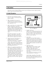
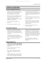
Страница 3: ...wheads and control shafts The current measured should not exceed 0 5 milliamp Reverse the power plug prongs in the AC outlet and repeat the test Fig 1 1 AC Leakage Test 6 Antenna Cold Check With the unit s AC plug disconnected from the AC source connect an electrical jumper across the two AC prongs Connect one lead of the ohmmeter to an AC prong Connect the other lead to the coaxial connector 7 X ...

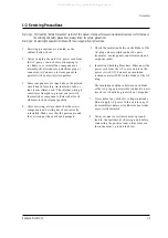
Страница 4: ...eated or that are otherwise damaged should be replaced with parts that meet the original specifications Always determine the cause of damage or overheating and correct any potential hazards 15 Observe the original lead dress especially near the following areas Antenna wiring sharp edges and especially the AC and high voltage power supplies Always inspect for pinched out of place or frayed wiring D...

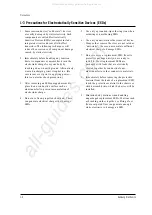
Страница 5: ... examples metal panels input terminals and earphone jacks 6 Insulation Checking Procedure Disconnect the power cord from the AC source and turn the power switch ON Connect an insulation resistance meter 500V to the blades of the AC plug The insulation resistance between each blade of the AC plug and accessible conductive parts see above should be greater than 1 megohm 7 Never defeat any of the B v...

Страница 6: ...se only a grounded tip soldering iron when soldering or unsoldering ESDs 6 Use only an anti static solder removal device Many solder removal devices are not rated as anti static these can accumulate sufficient electrical charge to damage ESDs 7 Do not remove a replacement ESD from its protective package until you are ready to install it Most replacement ESDs are packaged with leads that are electr...

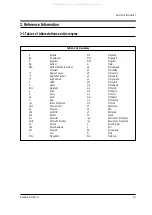
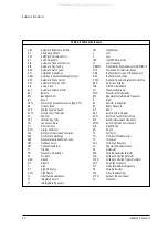
Страница 7: ...ond Kilowatt hour Kilogram Kilohertz Kilohm Kilometer Kilometer Per Hour Kilovolt Kilovolt ampere Kilowatt Liter Megahertz MV MW MΩ m µA µF µH µm µs µW mA mg mH mI mm ms mV nF Ω pF Ib rpm rps s V VA W Wh Megavolt Megawatt Megohm Meter Microampere Microfarad Microhenry Micrometer Microsecond Microwatt Milliampere Milligram Millihenry Milliliter Millimeter Millisecond Millivolt Nanofarad Ohm Picofar...

Страница 8: ... High Frequency High Fidelity Inductance Capacitance Integrated Circuit Intermediate Frequency I O L L LED LF MOSFET MTS NAB NEC NTSC OSD PCB PLL PWM QIF R RC RF R Y SAP SAW SIF SMPS S N SW TP TTL TV UHF UL UV VCD VCO VCXO VHF VIF VR VTR VTVM TR Input output Left Low Light Emitting Diode Low Frequency Metal Oxide Semiconductor Field Effect Tr Multi channel Television Sound National Association of ...

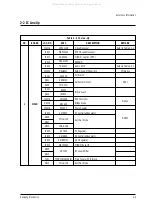
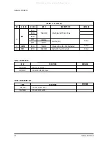
Страница 9: ... TDA7297 DRGB001 LA7845 KSD5703 FMP 3FU KA393 IRF620 3S1265R RBV606 PC123Y KA78R05 FML G12S FMG G26S KA7806 KA78R08 KA78RM33 KIA7025AP 2N7000 TCPN3081PA09A S FML G12S DESCRIPTION Video Processor NTSC Sound Processor MICOM Caption MTP EEPROM Audio AMP RGB Drive AMP Hybrid IC Vertical IC Horizontal Drive IC E W Drive IC SPS Controllor Bridge Diode Photo Coupler 5V Controlled Regulator Rectifier Diod...

Страница 10: ...F04 QF05 ICS01 ICP01 SPEC TDA6101Q 2SC2344 2SA1011 TEA6425 SDA9388X REMARK Option Option Option BOARD CRT V S W PIP Reference Information NO 2 3 4 SPEC VDP3108B VDP3130Y FUNCTION Basic 1H Comb Filter 2H Comb Filter DVD Input REMARK Table 2 3 1 VIDEO IC SPEC TDA7297 TDA7266S FUNCTION 7W x 2CH 10W x 2CH 3W x 2CH 5W x 2CH REMARK Table 2 3 2 SOUND AMP All manuals and user guides at all guides com ...

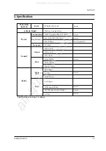
Страница 11: ...Back NTSC M PAL N M 160W Applied When 29 Flat Free Volts 100V 240Volts Free Voltage 50 60Hz 15W x 2CH 10W x 2CH 5W x 2CH Vitual Dolby Turbo Sound Pseudo Stereo RCA Input S VHS Head Phone 2 AV Input DVD Input YPbPr AV2 Monitor Audio Output S VHS 75ohms Coaxial Cable Not Present R815 Option Option Option Option Option Option Option Option All manuals and user guides at all guides com a l l g u i d e...

Страница 12: ...3 2 Samsung Electronics MEMO All manuals and user guides at all guides com ...

Страница 13: ...ussing A degaussing coil is mounted around the picture tube so that external degaussing after moving the TV should be unnecessary But the receiver must be properly degaussed upon installation The degaussing coil operates for about 1 second after the power is switched ON If the set is moved or turned in a different direction the power should be OFF for at least 10 minutes If the chassis or parts of...

Страница 14: ...il MRCR G B and MRWDG are green and those value are about 100 The incorrect SCREEN Voltage may result that MRCR G B and MRWDG should be red INCH CRT 14 SDI 15PF SDI 21 1 7R SDI 20V 10 0R SDI 21PF TSB 21PF LG 21PF SDI 25PF SDI 27V 1 3R SDI 27V 1 0R SDI 25V 1 0R SDI 23V 1 3R SDI No 1 2 3 4 5 6 7 8 9 10 11 12 IBRM 205 220 220 205 220 230 220 210 210 210 210 205 WDRV 35 35 35 35 35 35 35 35 35 35 35 3...

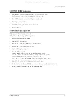
Страница 15: ... STANDARD from the menu 2 Input an 100 White pattern 3 Enter the Service Mode Refer to 4 8 Service Mode 4 Warm up the TV set at least for 30 minutes 5 Input a Toshiba pattern signal 6 Enter the Video Adjust1 Adjust Sub Contrast so that Y luminance becomes 65 ft 3 Use Red Drive and Blue Drive to adjust High Light x 265 y 265 Adjust Sub Bright so that Y luminance becomes 1 2ft 0 3 Use Red Cutoff and...

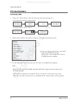
Страница 16: ...t parameters Note When CRT CRT PCB FBT E 2 PROM sometimes MICOM is replaced the adjustment values should be controlled After the Service adjustment is completed Do not select Reset in the service mode menu After above procedure is done power is on initially and the Plug and Play will be operated PICTURE OFF PICTURE ON MUTE 1 8 2 4 8 1 Service Mode These hexa digits are check sum value which depend...

Страница 17: ...X 0 0 0 0 0 0 PIP PAL V POS FIX 12 12 12 12 12 12 PIP NTSC V POS FIX 12 12 12 12 12 12 PIP H POS PIP H POS FIX 12 12 12 12 12 12 27V 1 3R 23V 1 3R 25V 1R 27V 1R 20V 1R 15 FLAT TXK2767 CL25D4W TXK2550 TXK2554 TXK2566 TXK2567 CL663BW TXK2750 TXK2754 TXK2060 TXK2066 TXK2067 CT 15A8 VIDEO ADJUST1 INIT RED CUT OFF 127 Control 127 127 127 127 127 127 GREEN CUT OFF 127 FIX 127 127 127 127 127 127 BLUE CU...

Страница 18: ...s 4 6 Samsung Electronics 4 8 2 B SCREEN CHANGE I2C BUS GEOMETRIC ADJUSTMENT 9 H Symmetry 5 H Corner 8 H Trapizium 4 H Parabola 10 H Shift 6 V Amp 3 H EW 2 1 V Shift V Slope 7 V SC All manuals and user guides at all guides com ...

Страница 19: ...l 52 52 52 52 52 52 SUB COLOR SUB COLOR 27 FIX 50 50 50 50 50 67 SUB TINT SUB TINT 30 FIX 70 70 70 70 30 15 BCL THRESHOLD BCL THRESHOLD 62 FIX 60 54 58 58 70 40 BCLGAIN 8 FIX 8 8 8 8 8 8 BCL TIME 13 FIX 10 10 10 10 10 13 DVD SUB TINT 90 FIX 100 100 100 100 100 120 N YC DELAY 0 FIX 3 3 3 3 3 4 27V 1 3R 23V 1 3R 25V 1R 27V 1R 20V 1R 15 FLAT TXK2767 CL25D4W TXK2550 TXK2554 TXK2566 TXK2567 CL663BW TXK...

Страница 20: ... INCH Model 27V 1 3R 23V 1 3R 25V 1R 25V 1R 27V 1R 27V 1R 20V 1R 20V 1R 15 FLAT 15 FLAT TXK2767 CL25D4W TXK2550 TXK2554 TXK2566 TXK2567 CL663BW TXK2750 TXK2754 TXK2060 TXK2066 TXK2067 CT 15A8 CT 15A8 VIDEO ADJUST3 INIT PEAK WHITE LIMLT PEAK WHITE LIMLT 255 FIX 255 255 255 255 255 255 SOFT LIMIT SLOPE B SOFT LIMIT SLOPE B 4 FIX 4 4 4 4 4 4 HARD LIMIT HARD LIMIT 255 FIX 255 255 255 255 255 255 MODUL...

Страница 21: ...5 FLAT TXK2767 CL25D4W TXK2550 TXK2554 TXK2566 TXK2567 CL663BW TXK2750 TXK2754 TXK2060 TXK2066 TXK2067 CT 15A8 G2 Adjust MRC R G B Max 110 110 110 110 110 110 MRWDG 110 110 110 110 110 110 IBRM FIX 210 205 210 210 205 220 WDRV FIX 35 35 35 35 35 35 CDL FIX 170 120 150 150 115 180 COL MIN 150 140 150 150 120 100 INCH Model INCH Model WHITE BALANCE INIT 4 8 2 G G2 ADJUST MODULATION ON OFF 0 FIX 0 0 ...

Страница 22: ...25 25 25 N YC DELAY 0 FIX 3 4 4 4 SIM 408A USA LATIN FACTORY VDP IC VDP3130Y INCH Model INCH INCH MODEL MODEL 4 8 3 A GEOMETRIC ADJUSTMENT VALUE 27V 1 3R 15 FLAT 21 FLAT 25 FLAT TXK2768 CL15A8 CL21A8 CL25A6 DEFLECTION INIT H Bow FIX 0 0 0 0 H Angle FIX 0 0 0 0 H Dscc FIX 3 2 2 3 V SHIFT 40 Control 27 35 27 50 V AMP 5 Control 50 20 6 15 V SLOPE 2 Control 7 4 6 2 V SC 7 FIX 6 6 6 6 H E W 64 Control ...

Страница 23: ...0 10 ACC REF 20 FIX 20 20 20 20 ACCR 21 FIX 21 21 21 21 INCH INCH Model Model INCH Model 4 8 2 D VIDEO 3 ADJUST 27V 1 3R 15 FLAT 21 FLAT 25 FLAT TXK2768 CL15A8 CL21A8 CL25A6 VIDEO ADJUST2 INIT B STRETCH BTHR 50 FIX 50 50 50 50 B DTRETCH BTLT 8 FIX 8 8 8 8 B STERTCH BAM 4 FIX 4 4 4 4 CORING 31 FIX 31 31 31 31 NTSC COMB FILTER 1 FIX 3 3 3 3 RGB BRIGHT 0 FIX 0 0 0 0 RG B CONTRAST 0 FIX 0 0 0 0 EHT TI...

Страница 24: ...10 MRWDG 110 110 110 110 IBRM FIX 210 220 220 210 WDRV FIX 35 35 35 35 CDL FIX 170 180 180 160 COL MIN 150 100 65 120 WHITE BALANCE WHITE BALANCE INCH Model INCH INCH Model Model 4 8 3 F G2 2 ADJUST 27V 1 3R 15 FLAT 21 FLAT 25 FLAT TXK2768 CL15A8 CL21A8 CL25A6 OTHERS INIT VSU 108 FIX 108 110 100 108 VSU2 0 FIX 0 0 0 0 H QE W 0 FIX 0 0 0 0 H ZOOM Parabola 8 FIX 22 8 8 12 H 16 9 Parabola 10 FIX 8 10...

Страница 25: ... I O I O PWM I O I O I O S D A 5 5 5 X Write Protect EEPROM SDA EEPROM SCL Bus Stop Main SDA Main SCL Sound Reset Video Reset VDD 2 5V GND VDD 3 3V CVBS Input VDD 2 5V GND AFT Scart1 Ident Scart2 Ident Key 1 H Sync V Sync Key 3 Key 2 X Ray Protect IR Input Stand By LED Time LED Tilt N C Power Sound Mute N C N C PX Y PX Y VDD 3 3V GND VDD 2 5V CORE OSD B OSD G OSD R VDD 2 5V GND X TAL Out X TAL In ...

Страница 26: ...y2 Input X Ray Protection Remocon Signal Input LED Drive Output Red LED Drive Output Green PIN NO 1 2 3 4 5 6 7 8 9 10 11 12 13 14 15 16 17 18 19 20 21 22 23 24 25 26 FUNCTION I O I O I O I O I O I O I O I O Vdd GND Vdd CVBS Vdd GND ADC ADC ADC ADC HS VS I O I O I O I O I O I O ASSIGN Write Protect ROM SDA ROM SCL Bus Stop Main SDA Main SCL Sound Reset Video Reset VDD 2 5V VDD 3 3V CVBS Input VDD ...

Страница 27: ... IN OUT Out In In Out Out Out Out Out In Out Out Out ACTIVE H L Low Low 6MHz 6MHz High Low DESCRIPTION Activate Degausssing Coil Not Used Programmed Gound Level Analog Ground Not Used Programmed Gound Level Not Used Programmed Gound Level Micom Hardware Reset Crystal Oscillation Input Crystal Oscillation Output Analog Ground Analog B OSD TTX Output Red OSD TTX Output Green OSD TTX Output Blue Fast...

Страница 28: ...4 16 Samsung Electronics MEMO All manuals and user guides at all guides com ...

Страница 29: ...D OFF Check IC901 Pin Check the voltage of IC803 805 Check H OUT of IC201 Pin Check IC908 and Replace IC901 Replace IC201 Check the voltage of IC803 805 Check Q401 and Horizontal Circuit Check FBT and B 130V Check IC902 Check SCL SDA Line Normal Normal Normal Normal Normal Replace IC902 Replace Q909 Q910 Check IC803 Check IC803 Check the voltage of IC804 Check the resistance of FD803 Replace FD803...

Страница 30: ...63 Check Fusible Resistance Check voltage of heater Check CRT and FBT Check the signal output from IC201 Pin Check R G B Signal input to CRT PCB Check R G B Signal Output from IC201 Check Check tuner B and Main CVBS Normal Normal Check Replace IC201 Normal Normal Check B 200V 16V Check Q501 and re adjust Screen Voltage Check the fusible resistance of abnormal volatge line Abnormal All manuals and ...

Страница 31: ...aker and Wire Check the signal input to IC601 Pin Check the signal input to IC602 pins Check IC602 B Replace IC602 Check Replace the resistance of FD802 Check tuner B and SIF Check IC601 B Check B Line 8V Check Replace IC601 Normal Normal Abnormal Abnormal Abnormal Normal Normal All manuals and user guides at all guides com a l l g u i d e s c o m ...

Страница 32: ...n screen Horizontal Lines Apper on screen Check IC201 Check IC301 B 16V 16V Check B Line and the fusible resistance of R425 424 Check the VDP Signal output from IC201 31 Pin Check Replace IC301 Normal Normal Abnormal Abnormal All manuals and user guides at all guides com ...

Страница 33: ...AKER 6W 8OHM 90DB 140HZ 2 1 6 AA61 40113A STOPPER PCB ABS HB NTR 1 1 7 AA64 40525A INDICATOR LED ACRYLCLR 1 1 8 AA64 40524A WINDOW REMOTE PCVIOLET 1 1 9 AA64 10803A KNOB CONTROL ABSHBBLK 1 2 AA03 00071A CRT COLOR A68AEG25X02 380MG 110 37 1 2 1 AA65 30113A CLAMP D COIL NYLON66 V2 BLK TVI25 29 4 2 2 AA60 10050R SCREW ASSY WC HH M5 L31 5 SWR 4 2 3 3704 001105 SOCKET CRT 11P 20PI 26 5PI NI 1 3 AA64 01...

Страница 34: ...1 00182AASSY CABINET FRONT 683B BK708 NO AV SA AA63 00097ACOVER AV TOOL 633B 683B MOLD 7 1 TXK2750X XAC TXK2750X XAC and TXK2754X XAA Dissimilar Parts Level Loc No Code No Description Specification Remark Level Loc No Code No Description Specification Remark 7 Electrical Parts List REMOCON AA59 10113HREMOCON DP TM59 AA59 10110H ASSY CABINET FRONT AA91 10351F1ASSY CABINET FRONT TXK2754 KS2A SECA AA...

Страница 35: ...C 560PF 10 500V C508 2305 000704 C M POLYESTER CFS922MTAPG250V1 C509 2201 000599 C CERAMIC DISC 560PF 10 500V C511 2401 000493 C AL 10UF 20 50V WT 5X11MM 5M C512 2401 000914 C AL 22UF 20 16V GP 5X11 5 TP C513 2301 000192 C FILM PEF 1NF 5 50V 5 3X10MM C514 2401 000430 C ELECTROLYTIC CE04WTAPG250V10 C515 2401 001232 C AL 4 7UF 20 250V GP 10X12 5 C516 2201 002063 C CERAMIC DISC 10nF 80 20 3KV Y5V TP ...

Страница 36: ...41Q 10V 100MA DO 34 TP D905 0404 000156 DIODE SCHOTTKY RB441Q 10V 100MA DO 34 TP D906 0401 000005 DIODE 1N4148 100V 300mA 1V 8nS TAPING D907 0402 000132 DIODE RECTIFIER 1N4004 400V 1A DO 41 D908 0401 000005 DIODE 1N4148 100V 300mA 1V 8nS TAPING DDR01 0402 000233 DIODE RECTIFIER FML G12S 200V H SINK DDR01 0402 001230 DIODE RECTIFIERFMG G2CS 1000V 3A TO 22 DDR01 1203 001006 IC VOLTAGEREGULATOR78R05 ...

Страница 37: ...N 15KOHM 5 1 8W AA TP 1 8X3 2MM R215 2001 000522 R CARBON 22KOHM 5 1 8W AA TP R216 2001 000429 R CARBON 1Kohm 5 1 8W AA TP 1 8x3 2mm R222 2001 000429 R CARBON 1Kohm 5 1 8W AA TP 1 8x3 2mm R223 2001 000628 R CARBON 300OHM 5 1 8W AA TP R224 2001 000628 R CARBON 300OHM 5 1 8W AA TP R225 2001 000628 R CARBON 300OHM 5 1 8W AA TP R226 2001 000628 R CARBON 300OHM 5 1 8W AA TP R228 2001 001170 R CARBON S ...

Страница 38: ... 5 1 2W AA R819 2004 001983 R METAL 2 49KOHM 1 1 2W AA TP 2 4X6 4 R821 2004 001889 R METAL S 127KOHM 1 1 2W AA TP 2 5X6 5 R822 2001 000273 R CARBON 100KOHM 5 1 8W AA TP R823 2001 000273 R CARBON 100KOHM 5 1 8W AA TP R824 2001 000660 R CARBON 33KOHM 5 1 8W AA TP R825 2001 000066 R CARBON S 10KOHM 5 1 2W AA R826 2001 001072 R CARBON S 12ohm 5 1 2W AA TP 2 4x6 4m R827 2008 000284 R FUSIBLE S 0 1OHM 1...

Страница 39: ...A59 10113B REMOCON DP TM59 AA59 10110B ASSY CABINET COM A BACK AA92 00406A ASSY CABINET COM CT27B3 SEA 27 AC BC AA65 30008A CLAMP CORD PE HB BLK B C AA64 01294A CABINET BACK TXK2750 54 CT27B3 HIPS VO B CB CF 6002 000514 SCREW TAPPING RH 2 M4 L15 ZP DRESB AA65 30018A CLAMP WIRE NYLON6 6 DATL FBT AA65 30109A CLAMP FBT NYLON 66 V2 BLK H T AA61 00356B HOLDER TUNER F JACK 501F ABS HB BLK INLAYB AA64 00...

Страница 40: ... ASSY PCB MAIN OPT AA94 02637AASSY PCB MAIN OPT KS2A 27 TXK2767 2701 000142 INDUCTOR AXIAL 1UH 10 2 5X3 AA94 02637A AASSY PCB MAIN COM KS2A 27 TXK2767 ASSY CABINET FRONT AA92 30240B1ASSY CABINET FRONT CT27B7 VO KS2A CCX AA92 00425A ASSY CABINET COM TXK2767 KS2A SECA AA64 00892E INLAY BACK D2 D3 RCA9P S VHS PS SHEET T0 ASSY VIDEO S W AA97 00726AASSY VIDEO S W CS7202GT7C EGC KS2A 1001 001114 IC VIDE...

Страница 41: ... 6X3MM C425 2201 000599 C CERAMIC DISC 560PF 10 500V C427 2401 002267 C AL 2 2UF 20 250V GP 8X12MM C429 2301 000232 C FILM PEF 3 3NF 5 50V 8 1X4 C504 2305 000704 C M POLYESTER CFS922MTAPG250V1 C505 2201 000599 C CERAMIC DISC 560PF 10 500V C506 2305 000704 C M POLYESTER CFS922MTAPG250V1 C507 2201 000599 C CERAMIC DISC 560PF 10 500V C508 2305 000704 C M POLYESTER CFS922MTAPG250V1 C509 2201 000599 C ...

Страница 42: ... 0402 000546 DIODE RECTIFIER TVR10G 400V 1 D804 0401 000005 DIODE 1N4148 100V 300mA 1V 8nS TAPING D808 0402 000132 DIODE RECTIFIER 1N4004 400V 1A DO 41 D810 0402 000132 DIODE RECTIFIER 1N4004 400V 1A DO 41 D811 0402 000132 DIODE RECTIFIER 1N4004 400V 1A DO 41 D813 0402 000233 DIODE RECTIFIER FML G12S 200V D816 0402 000546 DIODE RECTIFIER TVR10G 400V 1 D901 0404 000156 DIODE SCHOTTKY RB441Q 10V 100...

Страница 43: ...0 0505 000109 FET SILICON 2N7000 N 60V 200mA 5ohm 400 Q911 0501 000389 TRANSISTOR KSC815 Y TAPG YTAM QR01S 0501 000283 TRANSISTOR KSA539 Y TAPG YTAM QR02S 0501 000389 TRANSISTOR KSC815 Y TAPG YTAM R102 2001 000281 R CARBON 100OHM 5 1 8W AA TP R103 2001 000281 R CARBON 100OHM 5 1 8W AA TP R105 2001 000786 R CARBON 47KOHM 5 1 8W AA TP R106 2001 000864 R CARBON 56Kohm 5 1 8W AA TP 1 8x3 2mm R201 2001...

Страница 44: ...8W AA TP R625 2001 000429 R CARBON 1Kohm 5 1 8W AA TP 1 8x3 2mm R626 2001 000734 R CARBON 4 7KOHM 5 1 8W AA TP R666 2009 000022 R METAL PLATE 0 47ohm 10 5W CL TP 5x14x R701 2001 000969 R CARBON 75OHM 5 1 8W AA TP 1 R702 2001 000969 R CARBON 75OHM 5 1 8W AA TP 1 R703 2001 000969 R CARBON 75OHM 5 1 8W AA TP 1 R704 2001 000969 R CARBON 75OHM 5 1 8W AA TP 1 R705 2001 000969 R CARBON 75OHM 5 1 8W AA TP...

Страница 45: ...B3 25 KS2A SEA BATT 4301 000120 BATTERY MN 1 5V AA I B AA68 01218A MANUAL USERS ENGLISH W P100 KS2A ASSY CABINET FRONT A FRNT AA92 30240A1 ASSY CABINET FRONT CT27B7 VO KS2A UCX BADGE AA64 70117B BADGE BRAND AL SS R2000 25 SILVER CT 633 CDCOIL AA65 30113A CLAMP D COIL NYLON66 V2 BLK TVI25 29 CRT CF AA60 10050R SCREW ASSY WC HH M5 L31 5 SWR CW AA65 30105A CLAMP WIRE NYLON 66N VO NTR 15MM CWS AA65 30...

Страница 46: ...RAMIC MLC AXIAL 100PF 10 C244 2202 000121 C CERAMIC MLC AXIAL 100PF 10 C245 2202 000121 C CERAMIC MLC AXIAL 100PF 10 C247 2001 000362 R CARBON 150OHM 5 1 8W AA TP C301 2401 000603 C AL 1UF 20 50V GP 5X11MM 5MM C302 2401 000326 C AL 100UF 20 35V GP 8X11MM 5 C303 2201 000193 C CERAMIC DISC 10PF 0 25PF 50V C304 2305 000285 C FILM MPEF 220NF 5 100V 5M C305 2305 000178 C FILM MPEF 10NF 5 100V 5MM C306 ...

Страница 47: ...PO 5 0X3 0 5 C913 2401 000287 C AL 100UF 20 16V WT 6X11MM 5 C914 2305 000665 C FILM 104J 60V 5MM TAPING C915 2401 000287 C AL 100UF 20 16V WT 6X11MM 5 C916 2305 000665 C FILM 104J 60V 5MM TAPING C917 2401 001840 C AL 100UF 20 16V GP TP 6 3X1 C918 2401 001840 C AL 100UF 20 16V GP TP 6 3X1 C919 2305 000665 C FILM 104J 60V 5MM TAPING C920 2401 000480 C AL 10UF 20 50V GP 5X11MM 5M C921 2202 002037 C C...

Страница 48: ...UCTOR AXIAL 1UH 10 2 5X3 4 J706 2701 000142 INDUCTOR AXIAL 1UH 10 2 5X3 4 J707 2701 000142 INDUCTOR AXIAL 1UH 10 2 5X3 4 J713 2701 000142 INDUCTOR AXIAL 1UH 10 2 5X3 4 J909 2001 000429 R CARBON 1Kohm 5 1 8W AA TP 1 8x3 2mm JA701 3722 001333 JACK RCA9P 3 2mm NI BLK JA702 3722 001423 JACK RCA 3P S1P 3 4mm NI BLK L102 2701 000159 INDUCTORAXIAL 22uH 10 4 2x9 8mm L103 2701 000115 INDUCTOR AXIAL 10UH 10...

Страница 49: ...47OHM 10 2W AF R407 2001 000066 R CARBON S 10KOHM 5 1 2W AA R408 2008 000284 R FUSIBLE S 0 1OHM 10 2W AF TP 3 9X10M R409 2001 001410 R CARBON RD1 2T S 430 J43R R410 2001 001114 R CARBON S 270OHM 5 1 2W AA R411 2001 000281 R CARBON 100OHM 5 1 8W AA TP R412 2001 000020 R CARBON S 22OHM 5 1 2W AA T R413 2008 001018 R FUSIBLE S 0 47OHM 10 2W AF R414 2001 001165 R CARBON S 56OHM 5 1 2W AB T R415 2001 0...

Страница 50: ...W AA TP 1 R916 2001 000007 R CARBON 3KOHM 5 1 8W AA TP 1 R917 2001 000878 R CARBON 6 2KOHM 5 1 8W AA TP R918 2001 000009 R CARBON 20KOHM 5 1 8W AA TP R919 2001 000780 R CARBON 470ohm 5 1 8W AA TP 1 8x3 2mm R920 2001 000780 R CARBON 470ohm 5 1 8W AA TP 1 8x3 2mm R921 2001 000734 R CARBON 4 7KOHM 5 1 8W AA TP R923 2001 000924 R CARBON 680ohm 5 1 8W AA TP 1 8x3 2mm R924 2001 000429 R CARBON 1Kohm 5 1...

Страница 51: ...C AXIAL 100PF 10 CA04 2202 000720 C CERAMIC MLC AXIAL 8 2nF 20 16V Y5R TP CA05 2202 000720 C CERAMIC MLC AXIAL 8 2nF 20 16V Y5R TP CA06 2401 003102 C AL 100uF 20 10V GP TP 5x11 5 CA07 2401 003102 C AL 100uF 20 10V GP TP 5x11 5 CN01A AA39 20068E LEAD CONNECTOR ASSY YBNH025 08 67096 0 CN05A AA39 20069D LEAD CONNECTOR ASSY YBNH025 JE01 3722 000143 JACK PHONE 1P 3 4MM MBAG JR01 3722 001031 JACK RCA 3P...

Страница 52: ...8 Block Diagrams Samsung Electronics Schematic Diagrams 8 1 8 1 Power Diagram All manuals and user guides at all guides com ...

Страница 53: ...8 2 Block Diagram Schematic Diagrams 8 2 Samsung Electronics All manuals and user guides at all guides com ...

Страница 54: ... R R L G R L R L VO G VI G LO RO LI RI TO SPEAKER CN06A CN01A CN05A B Out G Out R Out Sense 8V GND Bo Vo CN501B CN502B CN501A GT804 GT102 CN701 CN502A CN602 Go Lo Ro Ro Se 8V GND 16V G G G Heater NC 180V Vi Li Ri 16V G Heat NC 180 220V All manuals and user guides at all guides com ...

Страница 55: ...9 2 Samsung Electronics MEMO All manuals and user guides at all guides com ...

Страница 56: ... TP04 TP10 10 Schematic Diagrams Samsung Electronics Schematic Diagrams 10 1 10 1 MAIN 1 4 WITH EW TP07 TP08 TP09 TP10 TP01 TP02 TP03 TP04 TP05 TP06 Power Line Signal Line All manuals and user guides at all guides com a l l g u i d e s c o m ...

Страница 57: ...TP12 TP13 TP11 TP14 TP15 10 2 MAIN 2 4 Schematic Diagrams 10 2 Samsung Electronics Power Line Signal Line TP11 TP12 TP13 TP14 TP15 All manuals and user guides at all guides com ...

Страница 58: ...4 Samsung Electronics Schematic Diagrams 10 3 TP16 TP18 TP17 TP19 TP20 TP21 TP22 TP23 TP24 TP25 Power Line Signal Line TP22 TP23 TP24 TP16 TP17 TP18 TP19 TP20 TP21 TP25 All manuals and user guides at all guides com ...

Страница 59: ...4 Schematic Diagrams 10 4 Samsung Electronics TP26 TP27 TP28 TP29 TP30 TP31 TP32 TP33 TP34 TP35 Power Line Signal Line TP32 TP33 TP34 TP35 TP26 TP27 TP28 TP29 TP30 TP31 All manuals and user guides at all guides com ...

Страница 60: ...10 5 POWER W O EW Samsung Electronics Schematic Diagrams 10 5 All manuals and user guides at all guides com ...

Страница 61: ...10 6 PIP Schematic Diagrams 10 6 Samsung Electronics All manuals and user guides at all guides com a l l g u i d e s c o m ...

Страница 62: ...Samsung Electronics 10 7 VIDEO SWITCH Schematic Diagrams 10 7 All manuals and user guides at all guides com ...

Отзывы: