Alignment and Adjustments
4-2
Samsung Electronics
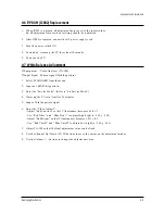
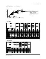
4-5 SCREEN Adjustment
1. Input Toshiba Pattern
2. Enter “Service Mode”.(Refer to “4-8-1 Service Mode”)
3. Select “G2-Adjust”.
4. Set the values as below.
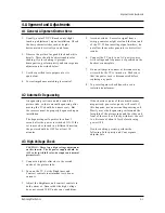
4-4 FOCUS Adjustment
1. Input a black and white signal.
2. Adjust the tuning control for the clearest picture.
3. Adjust the FOCUS control for well defined scanning lines in the center area of the screen.
5. Turn the SCREEN VR until “MRCR G B” and “MRWDG” are green and those value are about 100.
(The incorrect SCREEN Voltage may result that “MRCR G B” and “MRWDG” should be red)
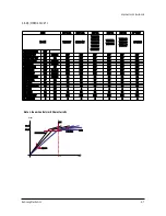
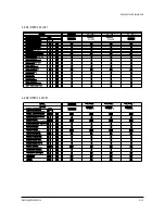
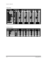
INCH / CRT
14” / SDI
15PF / SDI
21” 1.7R / SDI
20V 10.0R/SDI
21PF / TSB
21PF / LG
21PF / SDI
25PF / SDI
27V 1.3R / SDI
27V 1.0R/SDI
25V 1.0R/SDI
23V 1.3R/SDI
No
1
2
3
4
5
6
7
8
9
10
11
12
IBRM
205
220
220
205
220
230
220
210
210
210
210
205
WDRV
35
35
35
35
35
35
35
35
35
35
35
35
CDL
100
180
180
115
180
230
210
160
170
150
150
120
COLR G B
(Smallest Value)
100
100
100
120
65
65
65
120
150
180
180
140
Table 1. Screen Adjustment Table
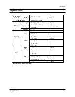
REGION
Normal
Содержание TXK2554
Страница 2: ...ELECTRONICS Samsung Electronics Co Ltd OCT 2000 Printed in Korea 3KS2A N 2507 ...
Страница 12: ...3 2 Samsung Electronics MEMO ...
Страница 28: ...4 16 Samsung Electronics MEMO ...
Страница 46: ...8 Block Diagrams Samsung Electronics Schematic Diagrams 8 1 8 1 Power Diagram ...
Страница 47: ...8 2 Block Diagram Schematic Diagrams 8 2 Samsung Electronics ...
Страница 49: ...9 2 Samsung Electronics MEMO ...
Страница 54: ...10 5 POWER W O EW Samsung Electronics Schematic Diagrams 10 5 ...
Страница 55: ...10 6 PIP Schematic Diagrams 10 6 Samsung Electronics ...
Страница 56: ...Samsung Electronics 10 7 VIDEO SWITCH Schematic Diagrams 10 7 ...


