Samsung Electronics
12-21
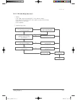
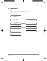
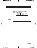
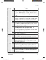
12-3-4 Outdoor Detailed Inspection Procedure
No
Procedure
Inspection Method
Cause
1
Wait 30 seconds over after
disconnecting the power
cable Check the outdoor
PCB.
1) Is C101 discharged?
2) Is the resistance of both terminals of C101 opened?
3) Is the fuse of EMI PCB normal?
4) Is the reactor wire connected?
• Over Current
• Inner short of PCB
• BLDC FAN Motor Error
2
Check the indoor unit
PCB.
1) Is R701 200ohm?
2) Does RY74 operate normally?
(IC05 & 16: 0V, 1: 5V)
3) Is the fuse(F701) normal?
4) Is the Sub PCB assembled normally?
• Outdoor PCB Error
• SUB Relay(RY74) Error
• IC05 Error
• Indoor PCB Error
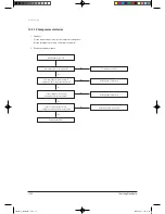
3
Check the LED lighting
after power supply.
1) Normal: Red: Light On, Green: Flickering, Yellow:
Light Off?
2) Is the voltage of C101 250V over?
3) Is the input of IC19 8V, and the output 5V?
4) Recheck after disassembling BLDC FAN Wire.
• Inner short of outdoor PCB
• Wrong assembly of outdoor PCB
• BLDC FAN Error
4
Check the condition of
indoor & outdoor connec-
tion cable.
1) Is the green LED light on once per second?
2) Is the indoor & outdoor connection able connected
in order?
3) Is the grounding wire connected to the both of
indoor & outdoor unit?
4) Is the voltage of terminal block N(1), 2 25V?
• Wrong connection of Indoor/Outdoor
wiring
•
Wrong assembly of outdoor
communication circuit
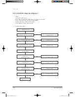
5
Check the Comp Wire.
1) Is it connected red, blue, and yellow in order in
counterclockwise.
2) Are the valve and its installation condition good?
3) Is the installation condition of outdoor unit?
•
Wrong assembly
•
Installation condition is bad.
6
Check the BLDC Fan.
1) Is CN01 1, 3 over 250V?
2) Is CN01 3, 5 within 1~5V?
3) Is the voltage of CN01 6 changed?
4) Is the resistance of BLDC Motor 1, 3 opened after
power off?
•
Outdoor PCB Error
• BLDC Motor Error
Troubleshooting
24867A(1)_TH026EAV_1.indd 21
2006-04-03 ソタタ・9:49:25


