Samsung SyncMaster170MP Скачать руководство пользователя страница 32


English     30


Appendix


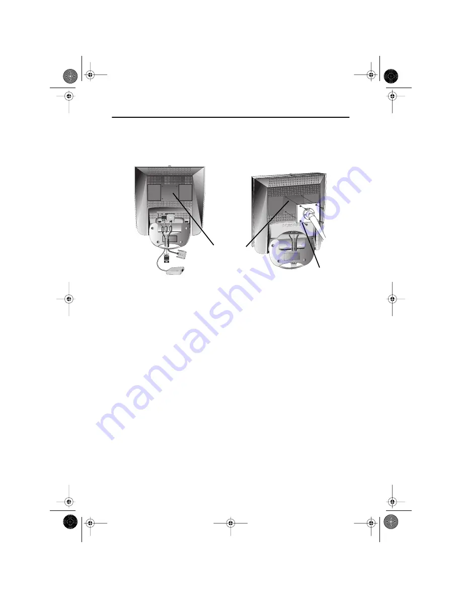
Installing VESA compliant mounting devices


Refer to page 32 to fold the base.

Align the mounting interface pad with the holes in the rear cover mounting pad and secure it
with the four screws that came with the arm-type base, wall mount hanger or other bases.


Wall Mount Instructions


The following instructions apply to a hollow sheet-rock wall only Tools/Hardware 
needed - Philips screwdriver, four toggle bolts, 5/8in dia. Drill bit and drill. Contact Ergotron at 
(800) 888-8458 to purchase the triple pivot direct mount adapter and wall mount bracket kit.


  • 150MP (15


") : 


No. 47 - 007 - 099 (Pivot direct mount adapter)

No. 97 - 101 - 003 (Wall mount bracket kit)


  • 170MP (17


")


 : 


No. 47 - 007 - 099 - 02 (Pivot direct mount adapter)

No. 97 - 101 - 003 - 00 (Wall mount bracket kit)

Align the wall mount bracket on the wall at the desired height, making sure that the bracket
will be mounted between the wall studs. Mark the four corner openings and drill four 5/8-dia.
holes.
Assemble the wall mount kit according to the instructions provided with it.
Securely attach Ergotron’s flat panel, triple pivot direct mount adapter to the back of the
monitor using the four 4mm, .7 pitch x 10mm screws provided with the arm.
Secure the assembly to the wall using four 3/16 by 3-inch long toggle bolts.

Mounting

Rear cover

mounting pad

4_E150MP170MPbody.fm  Page 30  Wednesday, September 19, 2001  2:54 PM

Содержание SyncMaster170MP

Страница 1: ...SyncMaster150MP SyncMaster170MP For PAL systems TFT LCD Monitor Owner s Instructions 1_E150MP170MPcov fm Page 1 Monday September 17 2001 5 05 PM ...

Страница 2: ...executing auto adjustment function in display screen that is appeared as window termination button is pressed If there s still noise after automatic adjustment use FINE COARSE adjustment function Information in this document is subject to change without notice 2001 Samsung Electronics Co Ltd All rights reserved Reproduction in any manner whatsoever without the written permission of Samsung Electro...

Страница 3: ...Controls 8 Automatic Save 9 Direct Access Features 10 OSD Lock Unlock 10 ON Screen Display OSD 11 Accessing the Menu System 11 OSD Functions and Adjustments 12 Appendix 19 By Remote Control 19 PowerSaver 21 Troubleshooting 22 Specifications 25 Pin Assignments 27 Display Modes 28 Installing VESA Compliant Mounting Devices 30 Wall Mount Instructions 30 Retractable Stand 31 Maintenance of Your LCD Mo...

Страница 4: ...rain or use it near water in kitchens near swimming pools etc If the LCD monitor accidentally gets wet unplug it and contact an authorized dealer immediately You can clean the LCD monitor with a damp cloth when necessary but be sure to unplug the LCD monitor first 9 Place the LCD monitor on a solid surface and treat it carefully The screen is made of thin glass with a plastic front surface and can...

Страница 5: ... Warranty Card Not available in all locations Installation CD Not available in all locations DC Adapter Power Cord Monitor 15 pin D Sub Signal Cable Scart Jack Remote Controller Batteries AAA x 2 Stereo RCA Cable option Stereo Stereo Cable 1 2 3 4 5 6 7 8 9 Display 0 Pre CH PAL NTSC Connector option Unpacking Your Monitor 4_E150MP170MPbody fm Page 3 Wednesday September 19 2001 2 54 PM ...

Страница 6: ...tly below your eye level when you are comfortably seated Viewing angle Tilt the screen until you feel comfortable working with your monitor Figure 1 Tilt the screen Kensington Security Slot This monitor offers you the opportunity to secure your monitor using a Kensington type secu rity device Kensington lock is not included Refer to your locking device documentation for in stallation instructions ...

Страница 7: ...nect the audio sources computer DVD VCR or Camcoder to proper Audio input ports Ain L Ain R or Ain stereo 5 Connect your external audio system to the Line out port 6 Connect your headphone to the Headphone out port 7 Connect antenna or CATV cable to Antenna port 8 Turn on both your computer and the monitor 9 If necessary install the video driver for the monitor See Installing the video driver on p...

Страница 8: ...es Installing the Video Driver The CD that accompanies this product contains the necessary drivers for installing your mon itor Please refer to the driver installation instructions included with your CD package for more information Self Test Feature Check STFC Your monitor provides a self test feature that allows you to check whether your monitor is function ing properly Make sure that PC is selec...

Страница 9: ... your monitor is functioning properly Getting Help If your monitor does not display an image check your cable connections and refer to Troubleshooting on page 22 If you experience difficulties with the quality of the displayed image run Auto Adjustment see page 12 and refer to Adjusting Your LCD Monitor on page 8 or Troubleshooting on page 22 Warm up Time All LCD monitors need time to become therm...

Страница 10: ...ription 1 Source Selects Video source Four source indicator LEDs on the left of the control button indicate currently active Video source 2 PIP Activates PIP Picture in Picture window directly PIP to Fullscreen video PIP off 3 Exit Exits from menus and sub menus Exits from the OSD system Turns the PIP off 4 Menu Opens the OSD and selects the highlighted function 5 Power Turns ON OFF the monitor In...

Страница 11: ...es It has 9 for 150MP 11 for 170MP factory preset or preload modes one for each signal frequency as listed in table 7 on page 28 If you have made no adjustments the on screen menu disappears and the monitor does not save anything 6 Moves the selector up or down on the OSD CH Increases or decreases the channel number 7 Moves the selector left or right on the OSD Increases or decreases the values of...

Страница 12: ...east 5 seconds to lock or unlock the controls When locked a LOCKED message will be displayed along the bottom of each OSD menu except for these screens Brightness Contrast Channel Volume Program Valid only after performing Channel auto program When OSD is not on the screen push the or button to select program channel number 1 Push the button to decrease channel number 2 Push the button to increase...

Страница 13: ...n then follow the Tool Tips to select the function and adjust the value 4 Use and buttons to select the sub menu and press the Menu button once to activate the selected sub menu 5 After selecting a function use the and buttons to make necessary adjustments The setting bar moves and the numeric value indicator changes to reflect your adjustments NOTE The numeric value indicator is provided as a poi...

Страница 14: ...djusted automatically Contrast Brightness Image Lock Image Lock is used to fine tune and get the best image by removing noises that creates unstable images with jitters and shimmers AUTO CH Menu Exit PIP Source TV V2 V1 PC VOL SyncMaster 150MP CH Menu Exit PIP Source TV V2 V1 PC VOL SyncMaster 150MP CH Menu Exit PIP Source TV V2 V1 PC VOL SyncMaster 150MP CH Menu Exit PIP Source TV V2 V1 PC VOL Sy...

Страница 15: ...r the image on the screen When Fine value is wrong WhenCoarsevalueiswrong Information Display current display mode Reset Image lock and position parameters are replaced with the factory default values H Position V Position Table 1 Screen controls Continued Icon Menus and Sub menus Function Descriptions CH Menu Exit PIP Source TV V2 V1 PC VOL SyncMaster 150MP CH Menu Exit PIP Source TV V2 V1 PC VOL...

Страница 16: ...w Position Change PIP window position TV Setup The channel system can be set in several different ways Channel system Select a channel system that is being used in your region See PAL broadcasting systems on page 29 CCIR AUSTRALIA Upon selecting a channel system you will be asked if you want to perform Channel auto program Select OK to perform the Channel auto program or select Cancel to select di...

Страница 17: ...lity and then select Save menu Now press Menu button to save the fine tuned channel Add Use this function to add a real channel Use buttons to select a desired channel and then select Add menu Now press Menu button to add the channel Cancel Use this menu to undo the current job Stereo System In most of the cases stereo system is automatically detected But in case you are experiencing audio problem...

Страница 18: ...nu them select Channel Delete to delete the selected channel Video Control This funtion is active if you select an input source other than PC DVD VCR TV Contrast Adjust the contrast of video or TV without affecting PC RGB s contrast Brightness Adjust the brightness of video or TV without affecting PC RGB s brightness Sharpness Adjust the sharpness of video or TV image Color Change the richness of ...

Страница 19: ...ize of the image being displayed can be handled in several different ways Expand1 Resize the image to fill the whole screen applicable to PC RGB only 150MP applicable to both PC RGB and video 170MP Expand2 Expand images keeping the original aspect ratio applicable to PC RGB only 150MP applicable to both PC RGB and video 170MP Normal Display the incoming image as it is applicable to PC RGB only 150...

Страница 20: ...n be changed Language English Deutsch Español Français Italiano Svenska Position Move the OSD Window to the vertical and horizontal direction Halftone Change the opaqueness of the background of the OSD Duration The number of seconds that the OSD will remain visible before disappearing Beep Enables or Disables the sound generated when you touch the control buttons Table 1 Screen controls Continued ...

Страница 21: ...rn on the OSD Turn off the OSD PIP Volume Channel Caption MTS mode USA or S mode Europe Channel search Power On Off Source PC V1 V2 TV Previous channel Display setup information Channel Stereo Mono Dual PIP Off PIP PC Full PIP PC PIP PIP on Full screen PIP Position 4_E150MP170MPbody fm Page 19 Wednesday September 19 2001 2 54 PM ...

Страница 22: ...the lower left corner of the screen Note SyncMaster150 170MP have an automatic stereo detection feature Thus depending on the types of audio the monitor automatically changes their audio mode from Mono to Stereo or vice versa Audio Type MTS S Mode Default FM Stereo Mono Mono Automatic Change Stereo Mono Stereo Dual Dual1 Dual2 Dual1 NICAM Mono Mono Automatic Change Stereo Mono Stereo Dual Mono Dua...

Страница 23: ...occurs when you move the computer s mouse or press a key on the keyboard This monitor is EPA ENERGY STAR compliant and NUTEK compliant when used with a computer equipped with VESA DPMS functionality For energy conservation turn your monitor OFF when you are not using it or when leaving it unattended for long periods State Normal Operation Power Saving Function mode EPA NUTEK Standby Mode Sleep Mod...

Страница 24: ...o sources Ensure that the PC or video sources are turned on Connecting your LCD monitor page 5 Sync Out of Range message Check the maximum resolution and the frequency of the video adaptor Compare these values with the data in the Display Modes Timing Chart Display Modes page 28 The image is too light or too dark Adjust the Brightness and Contrast Brightness page 12 Contrast page 12 Horizontal bar...

Страница 25: ...ty program to change the display settings Installing the Video Driver page 6 NOTE Your monitor supports multiscan display functions within the following frequency domain Horizontal frequency Vertical frequency Maximum refresh rate 150MP 30 kHz 69 kHz 170MP 30 kHz 81kHz 56 Hz 85 Hz 150MP 1024 x 768 85 Hz 170MP 1280 x 1024 76Hz Image is not centered on the screen Adjust the horizontal and vertical p...

Страница 26: ... volume is still too low after turning the control to its maximum check the volume control on the computer sound card or software program Refer to your computer sound card or software documentation Sound is too high pitched or too low pitched Adjust the Treble and Bass to appropriate level Audio Controls page 17 TV signal is not received Check Channel system and make sure you choose the correct ch...

Страница 27: ...ferent from this spec Frequency Horizontal Vertical Display color 30 69 kHz 56 85 Hz 16 777 216 colors 30 81 kHz 56 85 Hz XGA 60 76 Hz SXGA 16 777 216 colors Display Resolution Optimum Mode Maximum Mode 1024 x 768 60 Hz 1024 x 768 85 Hz 1280 x 1024 60 Hz 1280 x 1024 76 Hz Input Signal Sync Video signal H V Separate TTL P or N H V Composite TTL P or N Sync on green 0 3 Vp p N 0 7 Vp p 75 ohm TV Vid...

Страница 28: ... mm 6 5 kg 17 6 x 20 5 x 2 75 inch 14 3 lbs 448 x 522 x 70 mm 6 5 kg 22 5 x 24 8 x 7 95 inch 20 9 lbs 572 x 632 x 202 mm 9 5 kg Environmental Considerations Operating Temperature Operating Humidity Storage Temperature Storage Humidity 50 F to 104 F 10 C to 40 C 10 to 80 13 F to 113 F 25 C to 45 C 5 to 95 Audio Characteristics Audio Input 1 Audio Input 2 Line out Audio out Headphone out Frequency R...

Страница 29: ...DDC Return GND DDC Return 6 GND Red GND Red GND Red 7 GND Green GND Green GND Green 8 GND Blue GND Blue GND Blue 9 No Connection No Connection Not used 10 GND Sync Self Test GND Sync Self Test GND Sync Self Test 11 GND GND GND 12 DDC _SDA DDC _SDA DDC _SDA 13 H_Sync H V Sync Not used 14 V_ Sync Not used Not used 15 DDC _SCL DDC _SCL DDC _SCL 4_E150MP170MPbody fm Page 27 Wednesday September 19 2001...

Страница 30: ...mized during manufacture Table 7 Preset timing modes Mode Resolution Horizontal Frequency kHz Vertical Frequency Hz Pixel Clock Frequency MHz Sync Polarity H V VGA 720 x 400 31 469 70 087 28 322 640 x 480 31 469 59 940 25 175 640 x 480 37 500 75 000 31 500 640 x 480 43 269 85 008 36 000 SVGA 800 x 600 46 875 75 000 49 500 800 x 600 53 674 85 061 56 250 XGA 1024 x 768 48 363 60 004 65 000 1024 x 76...

Страница 31: ...ies 150MP 170MP PAL B G A2 CCIR Germany Austria Swiss Netherlands AUSTRALIA Australia NICAM CCIR Sweden Spain Denmark Norway Finland Belgium Iceland Portugal Malaysia Singapore Thailand Unknown CCIR India Israel Kuwait Jordan Yugoslavia I NICAM CCIR UK Hongkong 4_E150MP170MPbody fm Page 29 Wednesday September 19 2001 2 54 PM ...

Страница 32: ...15 No 47 007 099 Pivot direct mount adapter No 97 101 003 Wall mount bracket kit 170MP 17 No 47 007 099 02 Pivot direct mount adapter No 97 101 003 00 Wall mount bracket kit Align the wall mount bracket on the wall at the desired height making sure that the bracket will be mounted between the wall studs Mark the four corner openings and drill four 5 8 dia holes Assemble the wall mount kit accordin...

Страница 33: ...ssemble the monitor cabinet except for gaining access to the cable connectors as described on page 5 Users cannot service the monitor User maintenance is restricted to cleaning as explained below Unplug the monitor from the power outlet before cleaning To clean your flat panel display screen lightly dampen a soft clean cloth with water or mild detergent If possible use a special screen cleaning ti...

Страница 34: ...cushion or other soft materials to protect the screen 2 Remove the connector cover 3 Remove any cable connected on the monitor 4 Press FOLD button on the stand and tilt the monitor backward until the stand in up right position 5 Connect any cable you removed at step 3 6 Place the connector cover removed at step 2 7 Now you are ready to install Wall Arm mounting device depending on your application...

Страница 35: ...Display 11 OSD Lock Unlock 10 OSD Control 18 P PAL NTSC connector 3 PAL Broadcasting System 29 Pan 17 Pin Assignments 27 PIP 8 14 Plug and Play 6 Power 8 Power Indicator 6 Power saving modes 21 Program 10 R Remote Controller 3 19 Reset 13 S S VHS Cable 3 Safety Instructions 2 Scart Jack 3 Screen controls 12 Self test feature check 6 Sharpness 16 Size 14 Source 8 17 Speaker mute 17 Stereo RCA Cable...

Страница 36: ...ct Declaration of conformity for products Marked with FCC Logo ThisdevicecomplieswithPart15oftheFCCRules Operationissubjecttothefollowingtwoconditions 1 thisdevicemaynotcauseharmfulinterference and 2 this devicemustacceptanyinterferencereceived including interferencethatmaycauseundesiredoperation Thepartyresponsibleforproductcompliance SAMSUNGELECTRONICSCO LTD AmericaQALabofSamsung 85WestTasmanDri...

Страница 37: ...ics UK Ltd Samsung House 225 Hook Rise South Surbiton Surrey KT6 7LD Tel 0181 391 0168 Fax 0181 397 9949 European Service Center National Service Stafford Park 12 Telford Shropshire TF3 3BJ Tel 01952 292 262 Fax 01952 292 033 THAILAND Samsung Service Center 729 729 1 JSP Tower Rachadapisek RD Bangpongpang Yannawa Bangkok 10120 Tel 662 2954508 14 Fax 662 2954267 SOUTH AFRICA Samsung Electronics Sou...

Отзывы: