background image


SVR-1650/1640 User Manual 


71


9


SWR : If  the product is connected to a cable modem or a xDSL modem, IP    address will 
change each time connection to ISP (User’s communicaton company server) is attempted. In 
this case, the user will not know the changed IP address. If  a product using a floating    IP is 
registered on the SWR server, the changed IP can be found when attempting connection with 
the product. To register an IP    address on the SWR, setup [SWR] item to ON. Changed IP 
address can be verified from FUNCTION-STATUS (SYSTEM INFORMATION 2). 


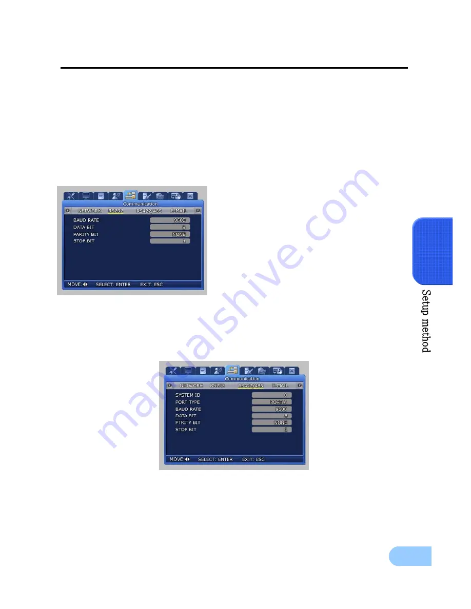
5.9.2 RS-232 

Setup items needed to connect with the computer connected to the product through the serial port. 


9


BAUD RATE : Setup the data transmission 
speed per second. 

9


DATA BIT : Setup the data transmission bit. 

9


PARITY BIT : Setup the error check method 
for data transmission. 

9


STOP BIT : Setup bit to include when data 
transmission has been completed. 


5.9.3 RS-422/485 

Setup items needed to connect the product with surveillance equipment like camera and CCTV. 


9


SYSTEM ID : Setup ID for DVR main body when connecting the product with equipment 
like a controller. 

Содержание SVR-1640

Страница 1: ...Recorder SVR 1650 1640 User s Manual Thank you for purchasing a Samsung Digital Video Recorder Before attempting to connect or operate this product please read these instructions carefully and save this manual for future use ENGLISH ...

Страница 2: ......

Страница 3: ...d party to take any responsibility on its behalf Product warranty does not cover cases of accidents negligence alteration misuse or abuse In addition no warranty is offered for any attachments or parts not supplied by the manufacturer The warranty period for this product will be for 2 years from the date of purchase The following cases are not covered by the warranty and payment is required for re...

Страница 4: ...n 16 Chapter 3 Installation method 20 3 1 Overall connection 20 3 1 1 Front connection method 20 3 1 2 Back connection method 20 3 2 Detailed connection 21 3 2 1 Rack mount 21 3 2 2 Video Audio connection 22 3 2 3 External connector 24 Chapter 4 Operation method 31 4 1 Preoperation inspection items 31 4 2 Connection of power supply 31 4 3 Live screen 31 4 3 1 FUNCTION screen display 32 4 3 2 Singl...

Страница 5: ...1 Quick setup 43 4 12 PIP 44 4 13 System information 45 4 14 SPOT 45 Chapter 5 Setup method 46 5 1 Menu organization 46 5 2 Initial value setup 48 5 3 Operation description 54 5 4 FUNCTION menu 55 5 4 1 LIVE PLAY mode 55 5 4 2 FUNCTION operation description 55 5 5 Menu screen description 58 5 6 Screen setup 59 5 6 1 Screen 59 5 6 2 Sequencing 60 5 6 3 Display 62 5 6 4 Covert 63 5 6 5 SPOT 63 5 7 R...

Страница 6: ...arch 80 5 12 Copy 81 5 13 Exit 82 Chapter 6 Network viewer program 83 6 1 Introduction 83 6 1 1 System requirements 83 6 1 2 Program installation 84 6 2 DVR MANAGER Function 85 6 3 VIEWER screen function 88 6 3 1 Name for each function 88 6 3 2 Image display section 89 6 3 3 Page control section 89 6 3 4 DVR status display section 91 6 3 5 Main button section 92 6 3 6 List display section 96 6 3 7...

Страница 7: ...connected to reduce electric shock risk During operation 9 Do not open the product cover except qualified personnel or system installer Opening the product cover may cause an electric shock 9 Do not plug multiple appliances into one power outlet Doing so may cause fire 9 Do not place dishes containing water or heavy objects on the product Doing so may cause a malfunction 9 Do not use in areas cont...

Страница 8: ... with at least 15cm of space between the cooling ventilation opening and a wall 9 To prevent falling install the product in a flat area Dropping the product may cause an injury or a malfunction 9 Avoid areas exposed to sun light or heat since they may cause deformation or a malfunction 9 If a camera is installed while the DVR is recording image in another channel may be disrupted Start the storage...

Страница 9: ...of This Product Waste Electrical Electronic Equipment Applicable in the European Union and other European countries with separate collection systems This marking shown on the product or its literature indicates that it should not be disposed with other household wastes at the end of its working life To prevent possible harm to the environment or human health from uncontrolled waste disposal please...

Страница 10: ...le This product is a digital video recorder that digitizes 16 channels of video input and stores it in the built in hard disk drive Product functions can be setup conveniently using the mouse and buttons on the front panel Samsung SVR 1650 1640 is a digital image recorder that can be used as security equipment in banks apartments and government and public offices It is a stand alone product with p...

Страница 11: ...y setup of video recording resolution and motion detection for each channel Video recording setup of up to 480 NTSC SVR 1650 120 NTSC SVR 1640 or 400 PAL SVR 1650 100 PAL SVR 1640 frames per second possible 352 240 or 352x288 CIF based Manual and scheduled recording possible Video loss detection function Record events sensor video loss motion detection and text in the event list Up to 5 seconds of...

Страница 12: ...g from a remote location is possible entire or 4 DIVISION screen selection is possible PC playback storage search function and DVR control function using the network viewer is possible Search and playback by time or by event from a remote location is possible 10 100Mbps Ethernet xDSL support Multiple DVR connection Others GUI and mouse for user convenience Convenient firmware upgrade function usin...

Страница 13: ...the following accessories Please verify whether all accessories are included at the time of purchase If any accessory is missing inquire at the point of purchase 2 3 Name and Function of Each Part 2 3 1 Front panel 3 4 1 2 5 6 7 8 9 10 11 12 16 13 14 15 17 19 20 21 22 23 24 25 26 18 27 ...

Страница 14: ...s in progress HDD display LED Indicates whether hard disk drive is in operation NETWORK display LED Indicates whether network is in connection ALARM display LED Indicates whether event is in detection 3 COPY display LED Indicates whether COPY is in progress Power supply section Category Function 4 Stand by button Turn product ON or OFF Playback and recording section Category Function 5 REC Start o...

Страница 15: ...emory Stick at the preset time 18 SEARCH Select data search mode 19 MULTI Convert to a divided screen 20 FUNCTION Display the LIVE screen menu for FUNCTION 21 PTZ Select PTZ mode 22 ENTER Store or execute the select options 23 ESC Return to the previous stage menu USB Audio Video section Category Function 24 USB1 USB2 USB3 Connection port for mouse USB Memory Stick and DVD RW 25 AUDIO OUT Output p...

Страница 16: ... controller speed dome camera SRX 100B connector 13 TERMINATION Switch for RS 485 termination resistor setup 14 USB Terminal to connect external equipment DVD RW CD RW etc 15 VGA OUTPUT Output port to connect the PC monitor 16 ETHERNET Main LAN connection terminal 17 AUDIO OUT Terminal for speaker output 18 AUDIO IN Terminal for microscope input Refer to Chapter 3 Installation method and Chapter 4...

Страница 17: ...lay 12 STOP Cancel playback mode 13 STEP Playback 1 frame 14 PLAY PAUSE Playback and pause 15 FAST High speed playback 16 DIR Change playback direction forward direction or reverse direction 17 Move cursor up in the setup menu 18 Move cursor down in the setup menu 19 Move cursor to the left in the setup menu 20 Move cursor to the right in the setup menu 21 ENTER Setup value selection execution 22 ...

Страница 18: ...l BNC spot composite Front 1 terminal RCA composite Loop BNC 16 CH output VGA output PC monitor RGB output PIP screen PIP screen size 240 160 Fixed on left top side PIP screen organization Small live screen inside the live entire screen Audio Items Specification Audio 4 channel audio input Line input level 1 0V 20kΩ Line output level 1 0V 1kΩ Storage method PCM method Electric Specification Items ...

Страница 19: ...m Specification Remote controller Infrared LED Max 5m Mouse USB Menu setup and DVR setup handling possible Dedicated controller SCC 3100 RS 485 Hard disk drive Items Specification Max no of mounts 4 Basic mount 1 built in Hard disk drive type EIDE ULTRA DMA 133 Min speed 7200rpm Recommended product Maxtor series Maxtor series recommended Model HDD capacity Buffer 6L160P0 160G 8M 7L250R0 250G 16M 6...

Страница 20: ...e SUPER HIGH MID LOW Pre Alarm Setup possible within maximum 5 seconds Post Alarm Setup possible within maximum 5 minuets Countries using NTSC USA Canada Japan Korea Taiwan Mexico etc Countries using PAL Australia Austria Belgium China Denmark Finland Germany England Nederland Italy Kuwait Malaysia New Zealand Singapore Spain Sweden Switzerland Thailand Norway etc Network Items Specification Gener...

Страница 21: ...n Event item Alarm motion detection video loss Playback speed and direction Forward direction reverse direction High speed search Fast forward 2 4 8 Max reverse 2 4 8 MAX Pause and frame playback Playback screen pause function function to reproduce one frame at a time from the paused state Password Item Specification 2 stage password 8 digit numeric code Admin Control all functions User Connect th...

Страница 22: ...s and external devices is as follows Mouse Memory stick Speaker TV Monitor Use only DVD RW CD RW Media MONITOR A2 CH16 CH15 CH14 CH13 CH12 CH11 CH10 CH9 CH8 CH7 CH6 CH5 CH4 CH3 CH2 CH1 MONITOR A1 MONITOR B RS 422 485 VGA USB3 4 TERM 2 TERM 1 CONSOLE RELAY OUT SENSOR IN ETHERNET AUDIO IN 1 AUDIO IN 2 AUDIO IN 3 AUDIO OUT AUDIO IN 4 RS 232C 1 2 3 4 1 2 3 4 Sensor Warning LED ATM POS Speed Dome Camer...

Страница 23: ...21 3 3 2 Detailed connection 3 2 1 Rack mount To mount the product the enclosed rack must be mounted first Mount sequence is as follows The enclosed rack mount is mounted on the product The product is mounted on the 19 inch rack ...

Страница 24: ...osed image quality may be adversely affected Input video system type NTSC PAL is recognized automatically when the product power button is pushed However if a CCTV using a different system type is connected to a CAMERA IN terminal during product operation the product must be turned OFF and ON again for proper automatic recognition of the input video system type Image input from each camera is outp...

Страница 25: ...tion Appropriate devices must be connected to store or output voice information Voice input Connect a RCA voice input terminal like a line level input to the AUDIO IN terminal in the back of the product To setup voice input set AUDIO to ON in the record setup screen in the Setup menu Refer to 5 7 Record setup for details Four voice inputs are each synchronized 1 1 with CH1 CH4 and voice output is ...

Страница 26: ...12 13 S8 S9 S10 S11 S12 S13 SENSOR 8 SENSOR 9 SENSOR 10 SENSOR 11 SENSOR 12 SENSOR 13 21 22 23 24 25 GND GND GND GND GND Ground Ground Ground Ground Ground MONITOR A2 CH16 CH15 CH14 CH13 CH12 CH11 CH10 CH9 CH8 CH7 CH6 CH5 CH4 CH3 CH2 CH1 MONITOR A1 MONITOR B RS 422 485 VGA USB3 4 TERM 2 TERM 1 CONSOLE RELAY OUT SENSOR IN ETHERNET AUDIO IN 1 AUDIO IN 2 AUDIO IN 3 AUDIO OUT AUDIO IN 4 RS 232C 1 2 3 ...

Страница 27: ...o Description No Description 1 NO1 Normal Open 14 D_IO 0 Digital I O 2 CM1 Common 15 D_IO 1 Digital I O 3 NC1 Normal Close 16 D_IO 2 Digital I O 4 NO2 Normal Open 17 D_IO 3 Digital I O 5 CM2 Common 18 D_IO 4 Digital I O 6 NC2 Normal Close 19 D_IO 5 Digital I O 7 NO3 Normal Open 20 D_IO 6 Digital I O 8 9 10 11 12 13 CM3 NC3 NO4 CM4 NC4 GND Common Normal Close Normal Open Common Normal Close Ground ...

Страница 28: ...Not connected 5 GND Ground GND Ground 6 N C Not connected N C Not connected 7 Tx Data Send Data PORT A Controller SCC 3100 Control 8 Tx Data Send Data 9 Rx Data Receive Data 10 Rx Data Receive Data 11 N C Not connected N C Not connected 12 N C Not connected N C Not connected 13 GND Ground GND Ground 14 N C Not connected N C Not connected 15 Tx Data Send Data PORT B Speed Dome Control 16 Tx Data Se...

Страница 29: ... terminal RS 422 485 connection can be selected from the SW1 switch To connect RS 485 SW1 switch 1 2 are turned ON To connect RS 422 SW1 switch 1 2 are turned OFF DVR PORT A Controller Terminal PORT 1 RS 485 RS 422 RX 1 or 8 8 RX 2 or 7 7 TX 1 TX 2 ...

Страница 30: ...28 PORT B SPD 2200 terminal Speed dome terminal DVR PORT B D 9 or 16 D 10 or 15 GND 13 If GND is connected a much sharper image quality can be seen TERM2 switch 1 2 must be set to ON ...

Страница 31: ... be seen TERM2 switch 1 2 must be set to ON SPD 2300 3000 3300 terminal DVR PORT B Speed dome terminal RS 485 RS 422 RXD 9 or 16 16 RXD 10 or 15 15 TXD 9 TXD 10 GND 13 TX Terminal for RS 232 communication RX Terminal for RS 232 communication If GND is connected a much sharper image quality can be seen RS 422 485 connection can be selected from the TERM2 switch ...

Страница 32: ...C Not connected 6 N C Not connected 2 RxD Data receive 7 N C Not connected 3 TxD Data send 8 N C Not connected 4 N C Not connected 9 N C Not connected 5 GND Ground No Description No Description 1 Red signal 75Ω 0 7Vp p 9 N C Not connected 2 Green signal 75Ω 0 7Vp p 10 GND 3 Blue signal 75Ω 0 7Vp p 11 GND 4 N C Not connected 12 N C Not connected 5 GND 13 HSYNC Horizontal synchronization 6 GND 14 VS...

Страница 33: ...supply After connecting the product with other equipment including the power supply cable turn ON the power by pressing the stand by switch button in front of the product When product is turned ON video signal presence is recognized automatically Even if there is a sudden power failure all setup value will be maintained If the product is setup to input a password when product is turned ON and OFF ...

Страница 34: ...s pressed icons for FUNCTION LIVE will be activated FUNCTION icon can be used to setup SPOT PTZ and PIP In the FUNCTION PLAY screen the following play screen will be displayed 4 3 2 Single channel screen display If Channel 1 16 button is pressed each channel is displayed using the entire screen ...

Страница 35: ...en If MULTI button is pressed once again a 4 DIVISION screen is displayed Each time MULTI button is pressed a divided screen is displayed following the order for divided screen types setup in Screen Setup SEQUENCING If Multi button is pressed in order display is changed in the following order 16 DIVISION 4 DIVISION 9 DIVISION screen ...

Страница 36: ...d Setup RECORD RECORD MODE in the menu scheduled video recording is carried out automatically according to the reservation setup REC button is not operational during scheduled video recording Video recording status display NNNN shown on the screen when the corresponding channel is not being recorded 0 is displayed and if there are no images is displayed N Normal video recording in progress S Sched...

Страница 37: ...ton is pressed images stored in the basic built in HDD can be setup by time periods and played As shown below date and time video recording was carried out is displayed If the desired date and time is entered and OK button is pressed images recorded for each channel during this time period can be viewed 4 5 2 Event search If EVENT is selected after SEARCH button is pressed a screen for selecting t...

Страница 38: ... Motion detection events 9 TEXT Text input events If number of video recording items exceeds the number that can be displayed on one screen use the buttons on the remote controller or the main body to move between pages If a video recording item is selected and ENTER button is pressed the corresponding video recording will be played To return to the EVENT LIST press the ECS button again ...

Страница 39: ...tton is as follows 9 STEP Frame play Press the STEP button from the video recorded screen to play it in a frame Each time the button is pressed a small frame is played 9 PLAY PAUSE If PAUSE button is pressed from the PLAY screen the PLAY screen is paused momentarily If the button is pressed again PLAY is resumed 9 STOP Press the STOP button from the PLAY screen to exit the PLAY mode 9 FAST FAST PL...

Страница 40: ...nversion If there is a video recording press the PLAY PAUSE button from the LIVE screen to get to the PLAY screen Press the STOP button from the PLAY screen to return to the LIVE screen Conversion from live to playback screen is only possible if a file for a video recording that occurred one minute ago with respect to end time exists If such a file does not exist a No Data message is outputted PLA...

Страница 41: ...ry stick The device connected to the product will be automatically recognized and displayed on the menu After selecting a storage medium select the channel for which COPY will be carried out and the i mage information START REC TIME END REC TIME After a selection is made between NO RMAL COPY and QUICK COPY COPY is started NORMAL COPY Standard COPY If a recording is in progress it is continued even...

Страница 42: ...ded USB memory stick SanDisk Transcend 512MB recommended 3 If DVD RW CD RW media are not detected please install a UDF reader RW CD detection program UDF reader is a freeware that can be easily searched and downloaded from the internet 4 Please make sure only authentic products are used If inauthentic products are used problems may occur Using new media products is recommended If DVD RW and CD RW ...

Страница 43: ...d on the front of DVR is pressed after the A button is selected focus is adjusted automatically 9 To exit the PTZ mode press the mouse right button or the ESC key PTZ mode can only be used in LIVE screen and cannot be setup in MULTI mode It must be setup as SINGLE mode in the LIVE screen 4 10 2 Preset setup 9 Select a desired channel from channel 1 16 in the LIVE screen and select the entire scree...

Страница 44: ...preset values setup in advance 4 10 4 Using OSD for the Speed Dome Camera 9 After pressing the PTZ button from the single screen if either the ENTER key in the front of the DVR or the mouse button is pressed after moving the cursor to OSD for the speed dome camera and the following message will be displayed PTZ OSD 9 OSD cursor for the speed dome camera may be moved up down and left right by using...

Страница 45: ...product 9 RECORDE MODE Manual Event or Schedul Event setup item 9 EVENT CHECK Can be set to OFF ALWAYS or TIMEZONE 9 TIME SETUP Setup the system time 9 DATE FORMAT Setup the date display format 9 LANGUAGE Language can be selected 9 AUDIO Select whether to store voice information along with images Press the ESC button after completing the setup to move to the completion screen If SAVE is selected h...

Страница 46: ...rom Live screen 1 Press the FUNCTION button and select the PIP icon 2 From the menu on the right side of the live screen select the desired channel 3 If the desired channel is selected with the mouse a small screen is displayed inside the screen 4 If mouse right button or the ESC button is pressed PIP mode is cancelled Play PIP from PLAY screen Same as PIP setup item in live screen ...

Страница 47: ...e screen above video recording program information and version IP address MAC address voice information can be verified If mouse right button or ESC button is pressed the information screen is closed 4 14 SPOT If FUNCTION button is pressed the FUNCTION screen is displayed If the SPOT icon is clicked from here the following screen is displayed If SPOT monitor is used it can be used like the MULTI f...

Страница 48: ...a ap pt te er r 5 5 S Se et tu up p m me et th ho od d 5 1 Menu organization Menu organization for DVR is as follows Quick Setup Screen Setup Record Setup Event Setup Communication System Setup Search Copy Exit ...

Страница 49: ...10 for details SAVE DO NOT SAVE NETWORK RS232C RS422 485 E MAIL SCREEN SEQUENCING DISPLAY COVERT SPOT RECORD PROGRAM EVENT MD RELAY TEXT SYSTEM HDD PASSWORD DATE SETUP PTZ TIME EVENT LOG COPY STATUS Screen Setup Record Setup Event Setup Communication System Setup Search Copy Exit ...

Страница 50: ...IME ORDER MULTI MODE VIDEO LOSS SKIP 3 sec CH1 16 CH1 CH16 4DIV A 4DIV E 9DIV A 9DIV B 16DIV 4DIV CH1 CH5 CH9 CH13 9DIV CH8 CH16 OFF DISPLAY DATE TIME HDD FREE SPACE RECORD STATUS TITLE REMOTE ID ON ON ON ON ON COVERT CH NUMBER LIVE COVERT PLAY COVERT CH1 16 OFF OFF SPOT TITLE DISPLAY SPOT MODE SPOT EVENT SCREEN ON MANUAL OFF Record setup Main menu Lower menu Initial value RECORD RECORD MODE PROGR...

Страница 51: ... S 10 S I 704 X 240 10 H 20 S 704 X 288 10 H 20 S J 704 X 240 10 H 15 S 704 X 288 10 H 15 S K 704 X 240 5 H 10 S 704 X 288 5 H 10 S L 704 X 240 5 H 10 H 704 X 288 5 H 10 H M 704 X 240 3 H 5 H 704 X 288 3 H 5 H N 704 X 240 5 M 15 S 704 X 288 5 M 15 S O 704 X 240 3 M 10 H 704 X 288 3 M 10 H P 352 X 240 30 S 30 S 352 X 288 25 S 25 S Q 352 X 240 20 H 20 S 352 X 288 15 H 15 S R 352 X 240 10 H 15 H 352 ...

Страница 52: ...M 4 S I 704 X 240 3 M 5 H 704 X 288 3 M 3 H J 704 X 240 1 M 3 S 704 X 288 1 M 3 S K 704 X 240 1 H 3 S 704 X 288 1 H 3 S L 352 X 240 7 S 9 S 352 X 288 6 S 7 S M 352 X 240 5 H 10 S 352 X 288 4 H 5 S N 352 X 240 3 H 5 S 352 X 288 3 H 5 S O 352 X 240 7 H 9 H 352 X 288 5 H 10 H P 352 X 240 3 H 5 H 352 X 288 3 H 5 H Q 352 X 240 1 H 5 S 352 X 288 1 H 5 S R 352 X 240 7 M 9 S 352 X 288 6 M 7 S S 352 X 240 ...

Страница 53: ...V LOSS POWER OFF TEXT SYNC CHANNEL DEVICE CHECK PROTOCOL LINES CH1 NORMAL OFF 1 Communication Main menu Lower menu Initial value NETWORK TYPE DHCP IP ADDRESS SUBNET MASK GATEWAY DNS PORT SWR Ethernet OFF 000 000 000 000 255 255 255 000 000 000 000 000 000 000 000 000 4000 OFF RS232 BAUD RATE DATA BIT PARITY BIT STOP BIT 9600 8 NONE 1 RS422 485 SYSTEM ID PORT TYPE BAUD RATE DATA BIT PARITY BIT STOP...

Страница 54: ...SWORD ADMIN PASSWORD SETUP POWER ON POWER OFF RECORD OFF PLAY BUZZER IF CHECKING FAILS 22222222 11111111 OFF OFF OFF OFF OFF OFF DATE SETUP TIME SETUP DATE FORMAT DAYLIGHT SAVING YY MM DD OFF PTZ CH NUMBER CAMERA ID MODEL CH 1 16 0 NONE Search Main menu Lower menu Initial value TIME START RECTIME END RECTIME SEARCH TIME The first RECTIME in recording The latest RECTIME in recording Same as END REC...

Страница 55: ...SVR 1650 1640 User Manual 53 5 Copy Main menu Lower menu Initial value COPY COPY STATUS 1 NONE GSA H10A 2 NONE 3 NONE 4 NONE NO DATA Exit Main menu Lower menu Initial value SAVE DO NOT SAVE ...

Страница 56: ...left and to the right 9 Move the cursor up and down 9 Used to increase or decrease the value to be setup 9 Move the cursor and press the ENTER button to select the corresponding characters 9 Press the ESC button to exit the current menu being setup 9 To move between character rows use the up down arrow buttons Operation using the remote controller 9 Move left right within the menu Push the button ...

Страница 57: ...nversion to the PLAY screen occurs For single screen mode setup in the PLAY screen PLAY functions SPOT MULTI D ZOOM and PIP can be setup If PLAY PAUSE button is pressed while in MULTI mode D ZOOM function cannot be setup 5 4 2 FUNCTION operation description MAIN If MAIN button is pressed from FUNCTION LIVE the convenient setup screen shown below is displayed If MAIN Menu setup is desired press the...

Страница 58: ... 9 SYSTEM INFORMATION 2 Displays VERSION IP ADDRESS MAC ADDRESS and AUDIO information SPOT If SPOT button is clicked the SPOT setup screen is displayed SPOT monitor can be used to view SINGLE or divided screen DISPLAY If MULTI button is clicked the MULTI setup screen is displayed Main monitor can be used for live observation in SINGLE screen or divided screen ...

Страница 59: ...en conversion function before using other function buttons If an Event is generated and EVENT SWITCH TO EVENT SCREEN is ON for Event Setup Automatic screen conversion function is halted for EVENT DISPLAY MAX TIME before resuming operation D ZOOM If D ZOOM button is clicked zoom function for the installed camera can be used PIP If PIP button is clicked screen within a screen can be viewed in SINGLE...

Страница 60: ...the mouse is used 9 Main menu Main menu corresponding to each tab can be selected 9 Sub menu Lower menu that can be setup from the main menu can be selected 9 Setup items Setup items for the lower menu can be modified 9 Useage method Usage method for the selected menu 9 Record setup may take some time Please wait until it is completed Main menu Sub menu Setup items Usage method ...

Страница 61: ... SCREEN SEQUENCING DISPLAY COVERT SPOT related setup values may be modified 5 6 1 Screen Select a channel among the 16 available and setup the channel name brightness and contrast for that channel Each channel can be setup separately like this TITLE User can setup a title for each channel A channel name consists of 10 characters including the channel number ...

Страница 62: ...omatic conversion in the following order MULTI MODE 9 SEQ CH NUMBER Setup the screen display duration for each channel Setup range is Channel 1 16 ALL 9 DWELL TIME Setup the conversion display duration Setup range is SKIP 1 99 sec 9 ORDER Setup entire screens that will be converted 9 MULTI MODE User can assign 4 DIVISION and 9 DIVISION screens directly ...

Страница 63: ...IVISION interval Setup display for a 9 DIVISION screen for 9 channels VIDEO LOSS SKIP ON OFF If setup as ON channels without image signals will be skipped automatically and only channels with image signals will be displayed in the screen ...

Страница 64: ...splayed 9 RECORD STATUS ON OFF If setup as ON video recording status display NNNN is displayed in the upper right area of the screen during video recording 9 TITLE ON OFF If setup as ON titles for Channel1 16 set by the user in the channel name lower menu is displayed in the live screen 9 REMOTE ID ON OFF If setup as ON ID number of the remote controller is displayed on the screen For details on v...

Страница 65: ...ack Covert is turned ON recorded images stored in HDD cannot be played back 5 6 5 SPOT Setup items for the SPOT monitor 9 TITLE DISPLAY Determines if title is to be displayed in the SPOT monitor 9 SPOT MODE For MANUAL setup screen channel is converted by the button located in front of the product For SEQUENCE setup screen is converted automatically in setup order to the SPOT monitor 9 SPOT EVENT S...

Страница 66: ...ord mode setups manual and scheduled recording mode 9 M E Manual setup If REC button is pressed video recording is carried out 9 S E Video recording is carried out automatically according to the setup reserved schedule 9 PRE EVENT DURATION The amount of time before an event is setup and automatic video recording is carried out for this amount of time 9 POST EVENT DURATION The amount of time after ...

Страница 67: ...mation Scheduled video recording mode can be used to setup the date and time when video recording will be carried out automatically 5 7 2 Record program PROGRAM can be used to adjust the FRAME RATE QUALITY and RESOLUTION to setup video recording for M E and S E A program may be selected or directly setup depending on the desired number of frames and resolution For event recording setup is possible...

Страница 68: ...1 200 2 3 4 9 120 3 6 8 17 100 3 6 9 17 60 7 11 17 34 50 7 12 17 35 32 13 21 32 63 32 11 18 27 54 16 25 42 63 126 16 22 36 54 108 8 51 84 126 253 8 43 72 108 217 4 101 169 253 506 4 87 144 217 433 352 240 SUPER HIGH MID LOW 320 288 SUPER HIGH MID LOW fps 3 8 2 3 1 5 0 8 fps 5 0KB 2 6KB 1 8KB 0 9KB 480 2 3 4 8 320 3 4 6 13 400 2 3 4 9 240 3 6 8 17 200 3 6 9 17 120 7 11 17 34 100 6 12 17 35 64 13 21...

Страница 69: ...EN Setup whether to convert the screen to the corresponding channel when an event occurs 9 EVENT DISPLAY MIN TIME Min retention time for the screen when an event occurs Amount of time to ignore an event if consecutive events are generated is set within 0 5 seconds 9 EVENT DISPLAY MAX TIME Max retention time for the screen when an event occurs is set within 0 99 seconds or allways Maintain current ...

Страница 70: ...used for motion detection 9 AREA SETUP Setup motion detection for each channel and specify the sensitivity and area with the mouse 9 AREA DISPLAY If motion is detected area related to motion can be displayed Area selection can be carried out by clicking the mouse icon on the screen or by turning the shuttle ring on the product to the right To cancel rotate the shuttle ring to the left Press the ri...

Страница 71: ...cted to the RELAY OUT terminal in the back of the product Blinking green box indicates the state before selection After selection it turns yellow 5 8 4 TEXT This setup allows material input with equipment like a POS System to be viewed with DVR equipment To match protocol with the input equipment HEADER and DELIMITER are assigned and line to output to the screen is setup ...

Страница 72: ... 9 IP ADDRESS Input the IP address obtained from the internet service company of the user 9 SUBNET MASK Input the SUBNET MASK address obtained from the internet service company of the user 9 GATEWAY Input the GATEWAY address obtained from the internet service company of the user 9 DNS Input the DNS address obtained from the internet service company of the user 9 PORT PORT assigned when connecting ...

Страница 73: ...tem to ON Changed IP address can be verified from FUNCTION STATUS SYSTEM INFORMATION 2 5 9 2 RS 232 Setup items needed to connect with the computer connected to the product through the serial port 9 BAUD RATE Setup the data transmission speed per second 9 DATA BIT Setup the data transmission bit 9 PARITY BIT Setup the error check method for data transmission 9 STOP BIT Setup bit to include when da...

Страница 74: ...econd 9 DATA BIT Setup the data transmission bit 9 PARITY BIT Setup the error check method for data transmission 9 STOP BIT Setup bit to include when data transmission has been completed 5 9 4 E MAIL The manager can verify details related to the generated event through the email 9 E MAIL CHECK If turned ON E MAIL notice function is activated 9 to Setup the E MAIL address to receive a transmission ...

Страница 75: ... the mouse detailed items may be viewed 5 10 1 System 9 LANGUAGE Select a language for the menu screen 9 KEY BUZZER ON OFF Select whether to generate sound for key strokes when using the remote controller or when manipulating keys 9 DEFAULT Use to get back the initial setup values the product was shipped with 9 If Yes is selected from the following screen it will be initialized ...

Страница 76: ...esolution of each channel on network board This mode is supported in only SVR 1650 9 REMOTE SETUP ON OFF Used to determine remote setup mode 9 DVR ALIAS Used to identify network name 9 REMOTE ID Used to setup REMOTE ID numbers In general a user cannot upgrade Upgrade must be carried out by a certified expert The resolution and framerate of REMOTE LIVE MODE is different according to Recording Setup...

Страница 77: ...mat the built in fixed HDD If YES is clicked in the confirmation dialog window formatting is carried out 9 HDD Setup can be for HDD1 HDD4 or ALL Selection of HDD for format and information for the selected item will be displayed 9 If HDD FORMAT button is pressed a dialog box verifying whether to format is displayed If HDD is initialized formatted all information stored in the disk is deleted Initi...

Страница 78: ...FF Select whether to input the password during setup 9 POWER ON ON OFF Select whether to input the password when product is turned ON 9 POWER OFF ON OFF Select whether to input the password when product is turned OFF 9 RECORD OFF Select whether remote setup on the network is possible 9 BUZZER IF CHECKING FAILS If wrong password is entered three times the buzzer will go off System user authorizatio...

Страница 79: ...creen 9 TIME SETUP Setup the time From the dialog box shown above use the mouse wheel or the buttons on the front of the product to modify the setup value Then select SET to make the assignment 9 DATE FORMAT Setup format to use for date notation Select from year month day month day year day month year 9 DAYLIGHT SAVING Setup whether to apply daylight savings time ...

Страница 80: ...el 9 CAMERA ID User can assign an ID between 0 255 for each camera 9 MODEL None SPD PELCO D PANASONIC SCC SRX Select the manufacturer for the connected camera Signal input from a camera is different for each manufacturer Please setup accurately for the corresponding model Models that can be used Samsung SPD SPD 2200 2300 2500 3000 3300 SRX 100B Pelco D Speed dome using Pelco D protocol Panasonic W...

Страница 81: ...rovided If ENTER key located in the front of DVR is pressed or if lower level menu is selected with the mouse detailed items may be viewed 5 11 1 Time search If a desired date and time that is within the range for dates and times the recordings were made is setup and OK button is pressed the video recording can be reproduced and viewed ...

Страница 82: ...cluding loss video sensor and motion detection is possible Items selected during event search can be played back If ESC key is pressed during playback returns to the event search window 5 11 3 Log search Log history for generated events can be verified ...

Страница 83: ...R key located in the front of DVR is pressed or if lower level menu is selected with the mouse detailed items may be viewed If USB and DVD RW CD RW storage is inserted a screen like the one shown below is displayed 9 STATUS Progress status for the current copy operation is displayed Please use recommended media Refer to page 40 for details ...

Страница 84: ...e applied when they are verified after the Save button is pressed 9 As shown in the screen below when setup has been modified and SAVE is pressed the setup functions are applied The setup functions can be cancelled by pressing Do NOT SAVE ...

Страница 85: ... Provides a wide variety of search methods for recorded content GUI screen automatic change depending on user PC resolution Provides separate Manager Backup program for the viewer Single and 4 9 16 divided screen function Provides PTZ camera control and event real time sensing function 6 1 1 System requirements Pentium IV 3 0Ghz or higher Hyper threading recommended HDD capacity Minimum of 120G re...

Страница 86: ...ically in the PC Basic path to the execution file is as follows C Program File SAMSUNG TECHWIN DVR Viewer Program installation from the website Viewer program can be downloaded by connecting to http www samsungcctv com and going to SUPPORT DOWNLOAD CCTV Copy the automatic compressed file Setup exe in My computer desktop screen and double click the Setup exe file to uncompress the file to the desir...

Страница 87: ...e password For Group item adding a new group from the local network modifying the name for an existing group and deleting a group is possible Password for initial execution is setup as admin To change the password press the Password Change button enter the current password and change to a new password 9 Click the Add button in the DVR 9 If the Search button is pressed a list of DVR newly connected...

Страница 88: ...VR main body must be entered accurately 9 If Append button is selected it is appended to the tree on the left side 9 If IP for a registered DVR is changed a list is later displayed if the Find button is clicked 9 If list for modified IPs is selected the Information Modify button is activated 9 If Search button is clicked registered IPs are changed to new IPs Port is fixed to 4000 since current mod...

Страница 89: ...after information receive is carried out the content is saved 9 List that has not been validated cannot be connected from the viewer 9 If the viewer is executed and the DVR is selected and then connected an image is displayed DVR main body ADMIN PASSWORD and USER PASSWORD must match DVR server setup Some of the functions in the menu that can be setup from the DVR main body can be setup through the...

Страница 90: ...itored from the client PC UI is changed to match user PC resolution The screen above shows a 1280 x 1024 image If no camera is connected the screen displays a black box 6 3 1 Name for each function Name for each DVR network viewer program function is as follows DVR status display section Page control section Image display section Main button section DVR list display section PTZ control section ...

Страница 91: ...om the and image display control front channel and back channel that cannot be seen in the image display section can be seen 9 Hides various buttons and status information and only displays images whose size is adjusted to match the user computer resolution Press ESC key to cancel 9 If less than 16 channels are selected DVR image in another page is automatically shown at the designated time 9 Reco...

Страница 92: ... the selected channel by 180 degrees Audio control and HDD display 9 Speaker volume is adjusted and if button is clicked speaker sound is muted 9 Microphone volume is adjusted and if button is clicked microphone sound is muted 9 For HDD display the yellow portion indicates the amount used 7CH 2006 02 05 13 53 23 Print option for printing Printed output ...

Страница 93: ...ay If the 4 buttons are clicked specific signals are sent to the DVR Search control 9 Assigns the play direction for the video recorded image 9 Moves to the front and back frame in the paused state 9 Move to the start end of the time period in 10 minute units in the paused state Example 12 35 15 12 30 00 12 35 15 12 39 59 9 Speed button Assigns speed for playing 1X 2X 4X 8X 16X can be assigned For...

Страница 94: ...he screen shown below DVR Manager Program lock 9 To prevent others from using the program when the program user leaves the computer unattended the screen that was being used is minimized as an icon in the lower right corner 9 To use the program again click the minimized DVR viewer program in the lower right corner and enter the password that was setup 9 Call the DVR Manager program ...

Страница 95: ...ndicate image status Storage folder and Delete Recoded Data to be used in the program Live connect disconnect 9 Connect the DVR selected by the user from the DVR list so that it can be viewed in real time 9 To halt the live screen coming in to the DVR press the icon above again ...

Страница 96: ...d and Get Info button is clicked time and channel information for the selected DVR is displayed 9 If desired time and channel for playback is selected and the button is pressed images recorded during that time frame are displayed 9 Even for video recording search and file search if a related setup item is displayed it can be selected and played ...

Страница 97: ...r DVR server is selected in DVR list on the left side if Get Info button is clicked the channel and the time period are displayed and then users can select a category for backup Log Functions used in the program are shown as a list If the Delete All button is clicked all logs in the list are deleted Termination Terminate the network viewer program that was being used ...

Страница 98: ...le for DVR list will be activated in light green color 6 3 7 PTZ control section 9 Pan Tilt Zoom Focus for the speed dome camera is adjusted 9 When Pan Tilt Zoom Focus is adjusted speed can be specified up to 6 steps 9 Zoom Focus expand focus Expand reduce focus adjustment can be carried out for the selected channel 9 The arrow keys for position control button controls the up down angle and left r...

Страница 99: ...the selected channel and a variety of other menu items may be used easily by using the popup menu 9 Selected channel is a function to control only the channel selected by the user and All channels is a function to control all 16 channels 9 View only the I Frame is a function which shows only the reference images among the images transmitted from the DVR server main body ...

Страница 100: ...roller is not operating Check the batteries and replace them if needed Aim the remote controller propely at the product remote controller receiver section during operation If product and remote controller ID is different make them the same Video is not recorded in the HDD Video recording may not be possible if HDD is at the end of its lifespan or if there are bad sectors Such HDD must be replaced ...

Страница 101: ...ater has entered the product If a liquid has been spilled on the product or if a foreign substance has entered the product If the product does not operate as described in this manual If the product has been seriously damaged after being dropped If there is a clear difference in performance ...

Страница 102: ...50 100 SVR 1640 fps CIF 352 x 288 Recording Mode Manual Event Schedule Event HDD 250GB 1HDD Up to 4HDD Backup DVD RW 3 USB 2 Front USB Flash Memory Drive Serial Interface RS 232C RS 485 422 RJ 45 Sensor Input Relay Output 16 4 Input Output 4 2 1 Front Audio Interface RCA Protocol TCP IP DHCP SMTP Software Network viewer Network Transport speed Max 480 SVR 1650 fps 120 SVR 1640 fps Max 400 SVR 1650...

Страница 103: ...Dimensions ...

Страница 104: ...0 8137 8139 Fax 82 31 740 8145 TIANJIN SAMSUNG OPTO ELECTRONICS CO LTD 7 Pingchang Rd Nankai Dist Tianjin 300190 P R China Tel 86 22 2761 4724 33821 Fax 86 22 2761 6514 SAMSUNG OPTO ELECTRONICS UK LTD Samsung House 1000 Hillswood Drive Hillswood Business Park Chertsey Surrey KT16 OPS Tel 44 1932 45 5308 Fax 44 1932 45 5325 SALES NETWORK ...

Отзывы: