COLOR CCD CAMERA
User Guide
16
COLOR CCD CAMERA
User Guide
17
Installation
1
8
8
1
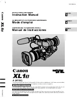
No.
Line Color
Camera to Power Supply
Power Supply to Receiver
1
White+Orange
VIDEO (+)
CH1
VIDEO (+) / RS-485 (+)
2
Orange
VIDEO (-)
VIDEO (-) / RS-485 (-)
3
White+Green
RS485 (+)
CH2
VIDEO (+) / RS-485 (+)
4
Blue
POWER (-)
VIDEO (-) / RS-485 (-)
5
White+Blue
POWER (+)
CH3
VIDEO (+) / RS-485 (+)
6
Green
RS485 (-)
VIDEO (-) / RS-485 (-)
7
White+Brown
POWER (+)
CH4
VIDEO (+) / RS-485 (+)
8
Brown
POWER (-)
VIDEO (-) / RS-485 (-)
Copper Connector
UTP Coating
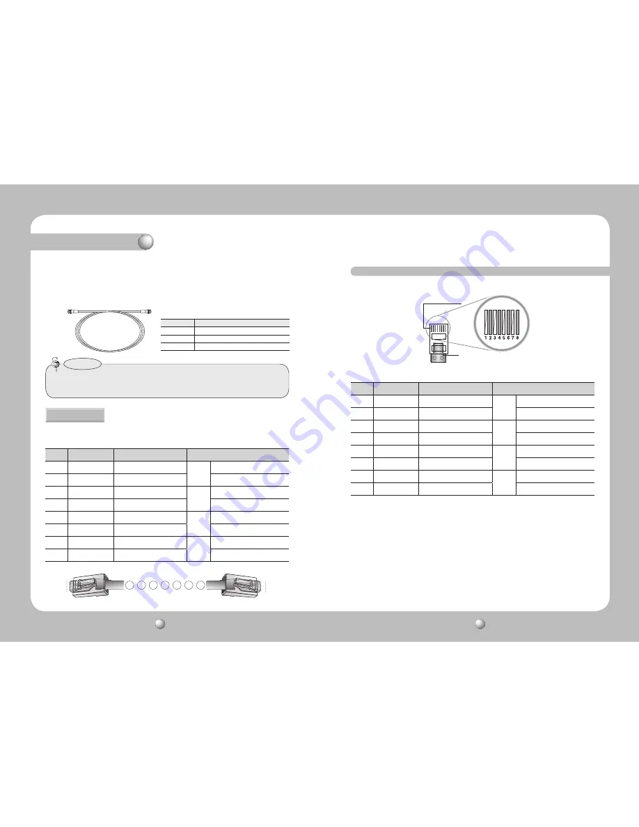
The SUB-2000 uses UTP cable to receive its power (AC 24V or AC28V) from the Power Supply.
Therefore, a separate adapter is not required. Please refer to the RJ-45 Connector Schematic
Diagram.
UTP CABLE
The camera uses UTP cable for transmitting video signals, power and transferring RS-485
control data.(TIA/EIA-568B)
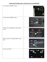
RJ-45 Connector Schematic Diagram
Distance
Recommended Cable Specification
300m
3C2V(RG-59/U)
450m
5C2V(RG-6/U)
600m
7C2V(RG-11/U)
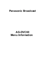
• Video Cable
The camera's video output port is connected to the monitor with a BNC coaxial
cable, shown below : If the distance between the camera and the monitor exceeds
the recommended maximum, please use an auxiliary video amp.
• It is recommended that pure copper coax cable is used and not copper coated
steel, as this will cause issues with the communication over the coaxial cable.
Notes


