background image

e-37

e-36

Chapter 4: DISPLAY MODE setting method

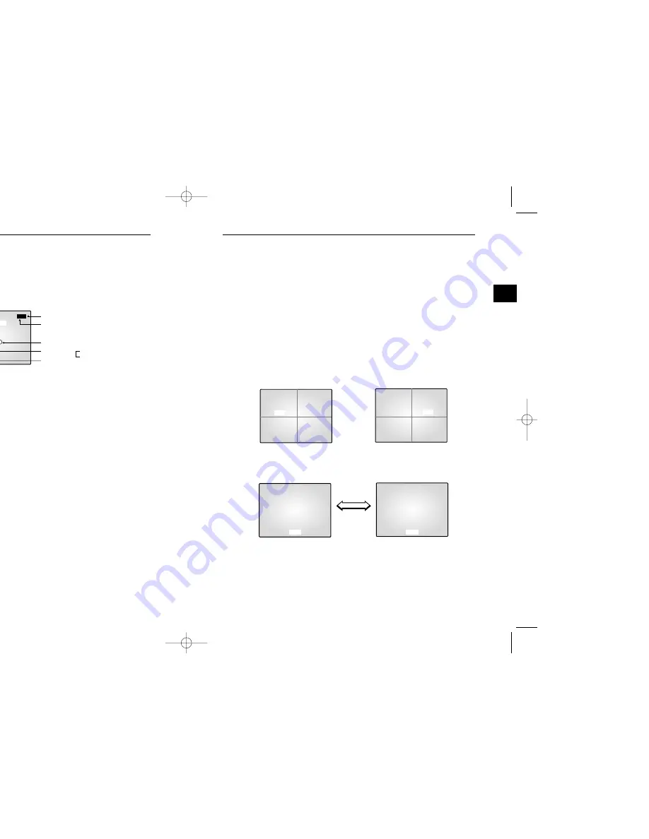
4-1)  SINGLE SCREEN DISPLAY   

The initial display mode is QUAD A mode. Use the UP and DOWN buttons to select the channel you

want to view on a single screen, and then press the ENTER button. The channel you selected will be

displayed on a single screen.

Alternatively, you can press the corresponding channel number key on the remote control to switch to a

single screen.

INITIAL DISPLAY STATUS

Select CAM2 by the
Up/Down button

FULL SCREEN DISPLAY of CAM2

FULL SCREEN DISPLAY of CAM1

Press ENTER

button after

selecting CAM2

Display
CAM1 by
Up/Down
Button

09/01/03 12:30:00

QUAD-A

CAM3                              CAM4

09/01/03 12:30:00

QUAD-A

CAM3                              CAM4

09/01/03 12:30:00

09/01/03 12:30:00

CAM1                              CAM2

CAM1                              CAM2

CAM 1

CAM 2

3-5)

EVENT LIST MENU function setting  

You can check the ALARM/LOSS EVENT LIST. If you click the UP/DOWN button to select 

5. EVENT LIST in the SETUP MENU and click the ENTER button, the following screen will be 

displayed.

The latest information on Alarms and Loss Detects will be stored.

This system stores up to 50 events (10 x 5 pages) staring from the latest one.

You can click the UP/DOWN button to check the list of other pages.

Press the MENU button to return to the SETUP MENU.

[EVENT LIST]                                         1 /  5

MM/DD/YY  HH:MM:SS    CH

1. 08/01/03   12:30:01   A  01

2. 08/01/03   12:29:01   L  03 

3. 08/01/03   12:28:01   L  01

All Pages

Current Page

Information on the Channel 
Where an Event Took Place

Event Information

Event Occurrence Time

A:Alarm
L:Loss

 00403A SSC-17TQ_ENG  10/9/03 11:30 AM  Page e-36

Содержание SSC-17TQ

Страница 1: ......

Страница 2: ...outed so that they are not likely to be walked on or pinched by items placed upon or against them paying particular attention to cords at plugs convenience receptacles and the point where they exit from the appliance 12 Lightning For added protection for this video product during a lightning storm or when it is left unattended and unused for long periods of time unplug it from the wall outlet and ...

Страница 3: ... 4 4 PIP MODE DISPLAY e 40 4 5 ZOOM MODE DISPLAY e 41 Chapter 5 Each product feature SOD14C Standard Camera e 42 SMM PIRCAM PIR Camera e 43 SOQ 080N DIGITAL DUAL QUAD e 44 EGUARDS e 2 tem Components and Installation requirements for installation and safety e 6 nents e 7 mposition and installation method e 9 mposition and connecting method e 21 al connecting method for CAMERA and e 22 connection an...

Страница 4: ... the system too closely together or the location is poorly ventilated the system maintenance of the system may be difficult Sufficiently circulate the room and tightly fasten the cover of the main system to prevent downs due to environmental causes ide Do not arbitrarily open the cover at meets the following environmental conditions Be sure to maintain ures and humidity conditions given below C 40...

Страница 5: ...Used to connect the camera to the monitor e SENSOR jack Used to connect the sensor to the camera PIN NUMBER SPEC SPEAKER HOT VIDEO_OUT GND SPEAKER COLD AUDIO_OUT ALARM_OUT 12V DC cessories are included with the main system E DESCRIPTION 17 TFT LCD MONITOR DIGITAL DUAL COLOR QUAD SWITCHER NORMAL TYPE CAMERA PIR CAMERA STANDARD TYPE CAMERA BRACKET 6PIN SHIELD CABLE 6PIN SHIELD CABLE CBF POWER CORD B...

Страница 6: ...ll or ceiling using the supplied three screws M4 X L15 video location and tighten the bracket handle on the camera mount ews wall or ceiling 3 PIR Camera composition Lens It has a focal length of 3 8mm and makes it possible for you to observe a relatively wide area Speaker It outputs the sound signal which was transfered from the monitor Fresnel Lens An infrared focusing lens for increasing the se...

Страница 7: ...tting the relay signals to external devices during the PIR sensor 1 PIN NUMBER SPEC SPEAKER HOT VIDEO_OUT GND SPEAKER COLD AUDIO_OUT ALARM_OUT 12V DC PIN SPEC Power Input DC 12 Volts Back Up Ground Not Used Relay Output COM 350V 130mA N C Please consider the horizontal detection area and the vertical detection line when choosing an installation site 11 30 AM Page e 12 ...

Страница 8: ...sun Can cause burn or damage to internal options 2 Do not limit desired detection zone by interference of curtains screens potted plants etc 3 Also do not locate it in front of source of water oil vapors Avoid placement of heat source inside detection zone 4 Do not install outdoors 8 9 PIN Function Sensor Sensitivity On On Low On Off Normal Off On Normal Off Off High Alarm Led On Off Sensor On Sen...

Страница 9: ... R CAMERA SMM PIRCAM that can sufficiently support 5 times the weight of the equipments to be 2 6 at the bottom of the main unit by turning it counterclockwise and as you push it upward to detach it from the case rear force as doing so may damage the inside assembly e installation site and mark screw holes with a pencil indicated by the Drill a pilot hole for each pencil mark 5mm in diameter and a...

Страница 10: ...amera mount bracket to the wall using the supplied screws M4 X L15 Adjust the camera to target the video location and tighten the bracket handle on the camera mount bracket Install the camera on to the male screw of the Camera Mount Bracket by rotating the camera in clockwise lens ver to turn the screw indicated by the arrow in the illustration The lens body will move out 10 from the horizontal an...

Страница 11: ...erly connected Connection status checking method Turn on the monitor after connecting cameras and check if camera image is displayed The initial screen mode of monitor is quad mode If the camera is not connected to the monitor information on the video loss will be displayed on the black screen urning it in a counterclockwise direction and then adjust the camera handle turning it clockwise and lock...

Страница 12: ...tem 1 6 Whole System connection and configuration e 23 OUT VCR TIME LAPSE REAR TFT LCD MONITOR DUAL QUAD BOX nnecting method for CAMERA and ecting method for CAMERA r external sensor can also be connected can be connected as shown in the above graphic O Normal Open ld separately terminals connecting method of Quad rear erminals in the rear of the Quad are VIDEO terminals for outputting TION CAMERA...

Страница 13: ... CABINET BOTTOM and then screw the BH M3X6 screws into the specified screw holes 2 Once the BRACKET GUIDE is assembled onto the SET use the BH M4X20 screws to fix it to the location you want n minals You Can connect up to 8 Cameras with RJ 11 connectors nals ng a 6 Pin connector input output terminal for the VCR input output terminal for the VCR n an alarm occurs the Active Make signal is output a...

Страница 14: ... is displayed TE CONTROL n and Using Method OCON is contained in the 17 TFT LCD 2 1 TALK KEY TALK KEY allows users to transmit voice signal to intended camera by inputting voice with built in MIC in the front of the monitor For this function select a target camera with the œ œENTER SWITCH on the FRONT PANEL if a voice signal is generated through the MIC with the TALK KEY pressed the signal will be...

Страница 15: ...ause eze mode all keys other than the ZOOM key will be disabled Other e the Freeze mode is canceled ntially This means that display the picture will be displayed during the WELL MENU of SETUP MENU and switch the picture automatically fer to Chapter 3 DWELL TIME MENU function and setting method for g bling it in the display If the ZOOM BUTTON is pressed zoom area DOWN LEFT RIGHT buttons to move the...

Страница 16: ...in the order of 0123456789 ABCDEFGHIJKLMNOPQRSTUVWXYZ _ Repeat the same to select all the desired letters You can choose up to ten letters CHANNEL TITLE CH1 CAM1 CH2 CAM2 CH3 CAM3 CH4 CAM4 CH5 CAM5 CH6 CAM6 CH7 CAM7 CH8 CAM8 each item function at SETUP of the FRONT PANEL allows users to enter SETUP MENU and see the ing method of each SETUP MENU function and operation is as follows SET MENU functio...

Страница 17: ...of the monitor and remote control 1 The value of the Monitor ID can be set from 0 to 9 by accessing the SYSTEM ID Setup mode under the SYSTEM SET menu Press the SYSTEM ID button on the remote control to display the Monitor ID and the Remote Control ID as shown above Enter the desired number by pressing the corresponding button 0 to 9 to set up the Remote Control ID The OSD will disappear four seco...

Страница 18: ...N CH2 ON ON CH3 ON ON CH4 ON ON CH5 ON ON CH6 ON ON CH7 ON ON CH8 ON ON U function setting D TIME EVENT BUZZER EVENT DETECT ton to select 4 EVENT SET in the SETUP MENU and click the creen will be displayed UP DOWN button and change the preset value with the after completing all the settings to return to the SETUP 1 MIN 03 MIN 05 MIN 10 MIN 20 MIN C 15 SEC 30 SEC be carried out for the duration of ...

Страница 19: ...CREEN DISPLAY of CAM1 Press ENTER button after selecting CAM2 Display CAM1 by Up Down Button 09 01 03 12 30 00 QUAD A CAM3 CAM4 09 01 03 12 30 00 QUAD A CAM3 CAM4 09 01 03 12 30 00 09 01 03 12 30 00 CAM1 CAM2 CAM1 CAM2 CAM 1 CAM 2 U function setting OSS EVENT LIST If you click the UP DOWN button to select MENU and click the ENTER button the following screen will be n Alarms and Loss Detects will b...

Страница 20: ...conds QUAD MODE SEQUENCE DISPLAY SINGLE MODE SEQUENCE DISPLAY 08 01 03 12 30 00 CAM 2 08 01 03 12 30 03 CAM 3 08 01 03 12 30 09 CAM 5 08 01 03 12 30 06 CAM4 08 01 03 12 30 00 QUAD A CAM3 CAM4 CAM1 CAM2 08 01 03 12 30 03 QUAD B CAM7 CAM8 CAM5 CAM6 08 01 03 12 30 06 QUAD A CAM3 CAM4 CAM1 CAM2 PLAY DISPLAY MODE and SEQUENTIAL DISPLAY MODE to QUAD A QUAD B to QUAD B QUAD A or PIP MODE to QUAD MODE m S...

Страница 21: ...ove the zoom area to the desired location Press œ œENTER SWITCH The selected area will be doubled and at FULL DISPLAY CAM 2 AY en mode use the UP and DOWN buttons to change the main channel and use the the main and sub screens In addition you can change the location of the T submenu of the SETUP MENU you push the sequence key channel of releated page Quad A or B e switching according to the dwell ...

Страница 22: ...5 Focal Length f 3 8mm F Number 2 0 Electronic Shutter lris Mounthy height 1 5m to 3m 5ft to 10ft Warm Up Period Max 50 seconds Spectral Response 5 to 14 um Sensitivity 4860 V W Detectivity 1 5 x 108 cm Hz 2 1 W Sensor Off On Alarm LED Off On 0 3 to 2 second Alarm Output NC 350V 130mA 40 dB Condenser Microphone Inclusion Modular jack RJ 11 10 50 C DC 12V Camera Sensor from Monitor DC 12V External ...

Страница 23: ...S ut Audio Out of VCR S Jack Type ut S Jack Type Relay Active Open Collector L Level Pulse Width 150ms or above Select 5 sec 15 sec 30 sec 1 min 3 min 5 min 10 min 20 min 30min or AUTO sec to 30 sec A mode Quad B mode PIP Sequence ore Live Mode Full Screen lusive of packing materials STEM 60Hz 11 30 AM Page e 44 ...

Страница 24: ......

Страница 25: ......

Отзывы: