Samsung SSA-S2000 Скачать руководство пользователя страница 50

50_


product specifi cations

product specifi cations

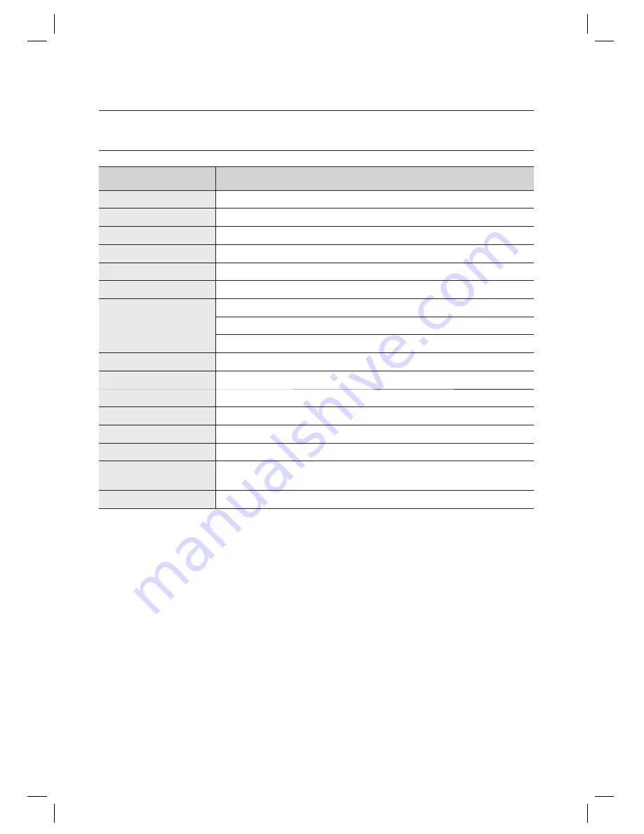
PRODUCT SPECIFICATIONS

Item

SSA-S2000

User 

512 Users 

Power / Current 

DC 12V / Max.110mA 

Reader Port 

External Reder Port 1ea : 26bit Wiegand for Exit

Reading Time (Card) 

30ms

Door Open Time 

00~99 Sec. (Default 3Sec.)

Input Port 

5ea : Exit Button, Door Sensor, Aux#1, #2, #3 

Output Port 

2ea : 2 Form-C Relay Output (COM, NO, NC) / DC12~18V, Rating Max.2A

1ea : Chime Bell Output / DC5V, Rating Max.500mA

1ea : TTL Output / DC5V, Rating Max.20mA

LED Indicator 

3 LED Indicators (Red, Green and Orange) 

Beeper 

Piezo Buzzer 

Keypad 

12 Key Numeric Keypad with Back Lighting 

Operating Temperature 

-30°C to +50°C

Operating Humidity 

10% to 90% relative humidity non-condensing 

Color / Material 

Silver with Black/ Polycarbonate 

Dimension (W x H x 
D(mm))

87.0 x 109.0 x 31.0

Weight 

220g

Содержание SSA-S2000

Страница 1: ...dalone RFID Access Controller user manual SSA S2000 imagine the possibilities Thank you for purchasing this Samsung product To receive more complete service please visit our website www samsungsecurity com ...

Страница 2: ... injury Do not place conductive objects e g screwdrivers coins metal parts etc or containers filled with water on top of the controller Doing so may cause personal injury due to fire electric shock or falling objects Do not install the unit in humid dusty or sooty locations Doing so may cause fire or electric shock If any unusual smells or smoke come from the unit stop using the product In such case ...

Страница 3: ...provided plug does not fit into your outlet consult an electrician for replacement of the obsolete outlet Protect the power cord from being walked on or pinched particularly at plugs convenience receptacles and the point where they exit from the apparatus Only use attachments accessories specified by the manufacturer Use only with cart stand tripod bracket or table specified by the manufacturer or so...

Страница 4: ...NAGEMENT 21 21 To register cards in RF ONLY mode 21 RegIsterIng cards In a combInatIon oF RF and P W modes 22 to regIster cards In PIn mode 22 regIsterIng cards In rF card PIn combInatIon mode 23 to delete a regIstered card or PIn number BASIC SETUP 24 24 Duress Alarm 24 To specify the retry count for an unregistered ID 25 To specify the keypad input suspension time if the retry count with an unre...

Страница 5: ...tered card user 40 To check the output specified for the Door Contact Sensor alarm 40 To check the output specified for AUX 1 41 To check the output specified for AUX 2 41 To check the output specified for AUX 3 I O TIME SETUP 29 30 To specify the output time if the card is not authenticated 30 To specify the Duress TTL output 31 To specify the alarm output for an input error of the Door contact Senso...

Страница 6: ...ou can use to register delete cards or configure various settings independently Buzzer On Off With the help of various buzzer tones you can check the operation status and the current settings and results of the product External I O Pins SSA SS2000 has 5 input ports and 4 output ports installed 2 relay and 2 TTL outputs The input ports can receive signals from the Exit button and the Door Contact se...

Страница 7: ...ollowing items are included in the product package X Y Z _ lzj lu W i zzhTzYWWW Main Unit Template O rings x5 x Gn 3 5 x 40mm Screws x4 3 5 x 12mm Screws x4 6 x 30mm Plastic Anchors x4 Quick Guide Diodes x2 UF4004 1N4001 4007 t Gj Master Card x1 Cables x4 CD Manual ...

Страница 8: ...n product introduction AT A GLANCE Front View System Status LED Indicates the operation status of the system Keypad Use this to configure or release settings as appropriate or enter a card number X Y Z _ lzj lu W i zzhTzYWWW ...

Страница 9: ...e Alarm Relay NO NO RL2 Purple Exit Button EXIT Orange Door Contact Sensor CONTACT Yellow with Red stripes Aux Input 1 AUX IN 1 Green Aux Input 2 AUX IN 2 Green with White stripes 7 PIN Connector I O Pins Signal Cable Color Wiegand Data Input 0 DATA_0 Pink Wiegand Data Input 1 DATA_1 Sky blue TTL Output TTL Orange with White stripes Chime Bell Output CHI Brown with White stripes Aux Input 3 AUX IN...

Страница 10: ...oosened Please check if the device is operating before fixing it If you try to remove the rear panel once it is fixed the lock parts of the rear panel will break resulting in a situation where the whole rear panel must be replaced J 2 05 52mm 1 85 47mm 3 03 77mm 1 52 38 5mm 1 52 38 5mm 1 55 39 5mm 1 79 45 5mm O ring O ring O ring O ring O ring 6 32 hole 6 32 hole 1 2 hole ...

Страница 11: ... Shielded Belden 9514 22 AWG 8 Conductor Shielded 3 Door Contact Sensor Exit Button Sensor Input Input This Product Belden 9512 22 AWG 4 Conductor Shielded Belden 9514 22 AWG 8 Conductor Shielded 4 Door Lock Alarm Device Lock Alarm This Product Belden 9409 18 AWG 2 Conductor Unshielded Belden 9409 18 AWG 2 Conductor Unshielded The cables should be thick enough to allow the maximum current consumed...

Страница 12: ...he black line Exit Button Connection Connect one line of the Exit button to the orange line Connect the other line of the Exit button to GND Door Contact Sensor Connection Connect one line of the door contact sensor to the yellow with red stripes Connect the other line of the door contact sensor to GND Auxiliary Input Device Connection AUX 1 green AUX 2 green with white stripes AUX 3 green with re...

Страница 13: ...he door to the plus line of the door lock Connect the minus line of the door lock to GND Alarm Connection Alarm Relay Connect the relay COM white for the alarm device to DC 12V Connect the relay NO line purple for the alarm device to the plus line of the alarm device Connect the minus line of the alarm device to GND Chime Bell Connection the chime bell operated by TTL level signal must be installe...

Страница 14: ...f the power supply unit to the minus line of the reader Connect the Wiegand data input line 0 of the proximity reader to the purple line Connect the Wiegand data input line 1 of the proximity reader to the sky blue line For a list of compliant readers external readers see the followings Standard 26bit Wiegand format proximity reader 1 2 3 4 X Y Z _ lzj lu W i zzhTzYWWW Wiegand DATA0 Pink Wiegand D...

Страница 15: ...ts the last can set the secure mode using the keypad Set Secure mode Press the 9 button twice and press ENT Release secure mode Present and authenticate a registered card or the Master Card to the reader You can use the keypad to specify the delayed start time for the Secure mode Refer to the delayed start time in Secure mode on page 28 For effective security purposes you can set to activate the s...

Страница 16: ...e with white stripes ON OFF ON OFF TTL Output Chime Bell Output OFF ON OFF ON Wiegand Data0 Wiegand Data1 In the 26 bit Wiegand output mode you can not initialize the product by short circuiting cables INITIALIZATION If you have the Master Card registered you can use it to initialize the device Present the Master Card to the device Press the 9 button twice and press ENT The system will restore the...

Страница 17: ...sembling it Use this method only if you have lost the Master Card or the password or if the forcible initialization with the external line failed Turn off the product and detach it from the installation site then loosen the screw x4 on each corner to disassemble it as shown Apply power to the product and short circuit the jumper for one second as shown When the initialization is completed 3 LED in...

Страница 18: ...shing of the 3 indicators denotes that the reader mode is already specified Press Button 0 and Button 1 in sequence and press ENT When the mode is specified only the green LED indicator flashes Present a card that you want to register as the Master Card to the device When the Master Card is registered only the red LED indicator flashes Present cards to register with the device one after another an...

Страница 19: ...ster PIN is ever registered If you remember the Master Card or the Master PIN was registered initialize the product and try again When you turn on the product all of the 3 LED indicators will flash with a beep No flashing of the 3 indicators denotes that the reader mode is already specified Press Button 0 and Button 3 in sequence and press ENT When the mode is specified only the green LED indicator...

Страница 20: ...If you don t want to register the cards right now simply jump to Step 5 above without through Step 4 above Present the registered Master Card to the product once again The device enters Standby mode with only the orange LED indicator flashing ENABLING KEYPAD INPUT FOR THE CARD NUMBER Ensure that you must have registered the Master Card Present the Master Card to the device Press Button 7 and Butto...

Страница 21: ... W MODES Ensure that you must have registered the Master Card and the device is specified in RF P W mode Present the Master Card to the device When the mode is specified only the green LED indicator flashes Press Button 1 and Button 2 in sequence and press ENT When the device enters Standby only the red LED indicator flashes Present a card to the device enter the 4 6 digit password and press ENT Repe...

Страница 22: ...ified in RF Card PIN combination mode Present the Master Card to the device When the mode is specified only the green LED indicator flashes Press Button 1 and Button 5 in sequence and press ENT When the device enters Standby only the red LED indicator flashes Present cards or PIN numbers 4 6 digits to register with the device one after another and the device will register them with a beep Repeat this ...

Страница 23: ...d Button 4 in sequence and press ENT When the device enters Standby only the red LED indicator flashes Present a card or PIN number to delete Repeat this step if you want to register multiple cards or PIN numbers Present the Master card to the device again and the device will switch to normal mode If no input is made for 20 seconds the device will switch to normal mode 1 2 3 4 X Y Z _ lzj lu W i zz...

Страница 24: ...ID You can specify the retry count for authentication with an unregistered card or PIN If the retry count exceeds the set limit the keypad input will be suspended for the next one minute You can specify the keypad input suspension time in To specify the keypad input suspension time if the retry count with an unregistered ID exceeds the limit on page 25 Present the Master Card to the device Press B...

Страница 25: ...e Master Card to the device Press Button 8 and Button 0 in sequence and press ENT Enter the two digit delayed start time unit minute and press ENT The default is set to 00 See the table below for your reference Secure Mode When the last person set the Secure mode before exiting the office the external sensors will get activated since then Delayed Start If the external sensors get activated right af...

Страница 26: ...press ENT The default is set to 00 second which means the Door Contact Sensor is disabled You can specify from 01 to 99 TO SPECIFY THE LIMITED TIME FOR THE KEYPAD INPUT When it passes a certain time during your setting using the keypad all your settings will be ignored and return to the initial state Specify the delay time between the input of the last key and restoring the previous state Present ...

Страница 27: ...ismantled device occurs regardless of the operation mode of either Normal or Secure so you simply specify the operation port only To specify the operation port refer to the operation port settings in the output port setting table on page 29 TO OPEN OR CLOSE THE ENTRY DOOR Follow the step below If you want to keep the door open regardless of the authentication process using the Master Card or PIN P...

Страница 28: ...ess ENT To release the QUICK mode repeat Step 1 above select the 4 4 buttons and press ENT The default is set to not used TO SET OR RELEASE THE TOGGLE MODE FOR THE DOOR RELAY In the Toggle mode the door opens if it is closed or vice versa by presenting a registered card or entering the PIN Present the Master Card to the device Press Button 4 and Button 5 in sequence and press ENT To release the To...

Страница 29: ... 02 Operate the TTL output only 04 Operate the door relay and TTL output 05 Operate the alarm relay and TTL output 06 TO SPECIFY THE OUTPUT TIME IF THE CARD IS AUTHENTICATED You can specify the output time if the card ID is authenticated When the card ID is authenticated the door relay and the TTL output operate for a set time Present the Master Card to the device Press Button 2 and Button 1 in se...

Страница 30: ...he alarm relay operates for 02 seconds in normal and Secure modes Other output ports that are not specified for the output mode will not be activated For instance if you set the output mode to 5 2 and assign the operation time for each output device by following the steps 4 5 and 6 above only the alarm relay will operate TO SPECIFY THE DURESS TTL OUTPUT If you enter the Duress code and present a re...

Страница 31: ...d For instance if you set the output mode to 5 2 and assign the operation time for each output device by following the steps 4 5 and 6 above only the alarm relay will operate TO SPECIFY THE ALARM OPERATION TIME FOR AUX 1 Present the Master Card to the device Press Button 2 and Button 5 in sequence and press ENT Refer to the output port table on page 29 and specify a desired output mode If you want...

Страница 32: ...above only the alarm relay will operate TO SPECIFY THE ALARM OPERATION TIME FOR AUX 3 Present the Master Card to the device Press Button 2 and Button 7 in sequence and press ENT Refer to the output port table on page 29 and specify a desired output mode If you want the alarm relay alone to operate in normal and Secure modes in case of an input through the auxiliary port select the 5 2 buttons and ...

Страница 33: ...eps the door relay active from the normal opening of the door to its closing This is useful when the door stays open with just one authentication Present the Master Card to the device Press Button 4 and Button 7 in sequence and press ENT To release the control by the Door contact Sensor repeat Step 1 above select the 4 8 buttons and press ENT The default is set to disabled 1 2 M X Y Z _ lzj lu W i...

Страница 34: ...H 5V to LOW 0V TO SET THE CHIME BELL FUNCTION You can specify the use of the chime bell Use the chime bell in the TTL level 5V for this purpose The default output time is 5 seconds For changing the output time refer to To specify the chime bell operation time on page 35 Present the Master Card to the device Press Button 7 twice and press ENT twice and press 7 8 buttons and press ENT The default is...

Страница 35: ... time from 00 to 99 seconds TO SPECIFY THE INPUT MODE FOR AUX 1 You can specify an operation for the auxiliary port 1 when it switches from LOW 0V to HIGH 5V Present the Master Card to the device Press Button 6 and Button 1 in sequence and press ENT To release the setting repeat Step 1 above select the 6 2 buttons and press ENT The default is set to switch from HIGH 5V to LOW 0V 1 2 3 M 1 2 M X Y ...

Страница 36: ... to switch from HIGH 5V to LOW 0V TO SPECIFY THE INPUT MODE FOR AUX 3 You can specify an operation for the auxiliary port 3 when it switches from LOW 0V to HIGH 5V Present the Master Card to the device Press Button 6 and Button 5 in sequence and press ENT To release the setting repeat Step 1 above select the 6 6 buttons and press ENT The default is set to switch from HIGH 5V to LOW 0V 1 2 M 1 2 M ...

Страница 37: ... switch from HIGH 5V to LOW 0V TO SPECIFY THE INPUT MODE FOR THE DOOR CONTACT SENSOR You can specify an operation for the Door Contact Sensor when it switches from LOW 0V to HIGH 5V Present the Master Card to the device Press Button 6 and Button 9 in sequence and press ENT To release the setting repeat Step 1 above select the 7 0 buttons and press ENT The default is set to switch from HIGH 5V to L...

Страница 38: ... device You must set the alarm mode when you have installed the device For the alarm output port settings refer to To specify the alarm output port for the dismantled device on page 27 Present the Master Card to the device Press Button 8 twice and press ENT To release the alarm setting for the dismantled device repeat Step 1 above select the 8 9 buttons and press ENT The default is set to disabled...

Страница 39: ...ess Button 3 and Button 1 in sequence and press ENT TO CHECK THE OUTPUT SPECIFIED FOR AN UNREGISTERED CARD USER You can check the output setting that you specified in To specify the output time if the card is not authenticated See page 30 Present the Master Card to the device Press Button 3 and Button 2 and Button ENT 1 2 1 2 X Y Z _ lzj lu W i zzhTzYWWW t G j X Y Z _ lzj lu W i zzhTzYWWW X Y Z _ l...

Страница 40: ... Master Card to the device Press Button 3 and Button 4 in sequence and press ENT TO CHECK THE OUTPUT SPECIFIED FOR AUX 1 You can check the output setting that you specified in To specify the alarm operation time for AUX 1 See page 31 Present the Master Card to the device Press Button 3 and Button 5 in sequence and press ENT 1 2 1 2 X Y Z _ lzj lu W i zzhTzYWWW t G j X Y Z _ lzj lu W i zzhTzYWWW X Y...

Страница 41: ...s Button 3 and Button 6 in sequence and press ENT TO CHECK THE OUTPUT SPECIFIED FOR AUX 3 You can check the output setting that you specified in To specify the alarm operation time for AUX 3 See page 32 Present the Master Card to the device Press Button 3 and Button 7 in sequence and press ENT 1 2 1 2 X Y Z _ lzj lu W i zzhTzYWWW t G j X Y Z _ lzj lu W i zzhTzYWWW X Y Z _ lzj lu W i zzhTzYWWW t G j...

Страница 42: ... flashes for 2 seconds Duress Mode Password 00 The TTL output port produces a signal for 3 seconds in Duress mode QUICK MODE Disabled Chime Bell Output Enabled Chime Bell Operating Time 0 5 second Melody Sound Enabled Keypad Input Limited Use 20 seconds When an input signal is sensed H L common for all inputs When a TTL output signal is sensed H L Patrol Mode Delay Time 00 minute Door Sensor Sensin...

Страница 43: ... 30 Set the TTL output time in Duress Mode Set the TTL output time in Duress Mode 14 31 To check the output of the registered card user test on code 21 To check the output of the registered card user test on code 21 15 32 To check the output of the unregistered card user To check the output of the unregistered card user 16 34 To check the output specified for the Door Contact Sensor alarm To check...

Страница 44: ...e Door Contact Sensor switches from L to H Sense if the Door Contact Sensor switches from L to H 41 70 Sense if the Door Contact Sensor switches from H to L Sense if the Door Contact Sensor switches from H to L 42 71 Set the TTL output to H Set the TTL output to H 43 72 Set the TTL output to L Set the TTL output to L 44 73 Keypad input enabled Keypad input enabled 45 74 Keypad input disabled Keypa...

Страница 45: ...r the user card or PIN number and provide the password according to the mode f Master Card or PIN 4 6 digits Mode 03 or 05 ENT For more information about registering the Master Card and the user card refer to the initial setup section in the user manual 2 If this happens while the product is operating normally with the Master Card and user card registered Product malfunction c Power OFF ON d If th...

Страница 46: ...T For more information about registering the Master Card and the user card refer to the initial setup section in the user manual 2 If this happens when you try to register an additional card in normal operation mode Register the user card only as the Master Card is already registered c Master Card or PIN 4 6 digits Mode 03 or 05 ENT d Command for an additional card registration according to the op...

Страница 47: ... to the initialization section in the user manual 2 If the problem persists after you have followed the procedures above contact a designated service center I lost the Master Card and could not register or delete the card or change the settings 1 YoumustinitializetheproductifyouwanttochangethedevicesettingswithouttheMasterCard orPIN InitializingtheproductwillrestoreallyoursettingsregardingtheMaste...

Страница 48: ...mand to change the keypad suspension time 60 ENT Enter a new time two digits ENT ex 10 ENT the keypad input will be suspended for 10 minutes For more information refer to the applicable section for the keypad suspension in the user manual If the buzzer stays inactive c Initialize the product Initializing the product will restore all your settings regarding the Master Card and user cards to the fac...

Страница 49: ...e shield line and space line as additional GND points Extend the Wiegand communication range along with the stable signal reception using the repeater f Formoreinformation refertotheexternalreaderconnectionsectionintheusermanual 3 If the problem persists after you have followed the procedures above contact a designated service center The door lock does not operate at all 1 Check if the door lock i...

Страница 50: ...Sensor Aux 1 2 3 Output Port 2ea 2 Form C Relay Output COM NO NC DC12 18V Rating Max 2A 1ea Chime Bell Output DC5V Rating Max 500mA 1ea TTL Output DC5V Rating Max 20mA LED Indicator 3 LED Indicators Red Green and Orange Beeper Piezo Buzzer Keypad 12 Key Numeric Keypad with Back Lighting Operating Temperature 30 C to 50 C Operating Humidity 10 to 90 relative humidity non condensing Color Material S...

Страница 51: ...Waste Electrical Electronic Equipment Applicable in the European Union and other European countries with separate collection systems This marking on the product accessories or literature indicates that the product and its electronic accessories e g charger headset USB cable should not be disposed of with other household waste at the end of their working life To prevent possible harm to the environ...

Отзывы: