background image

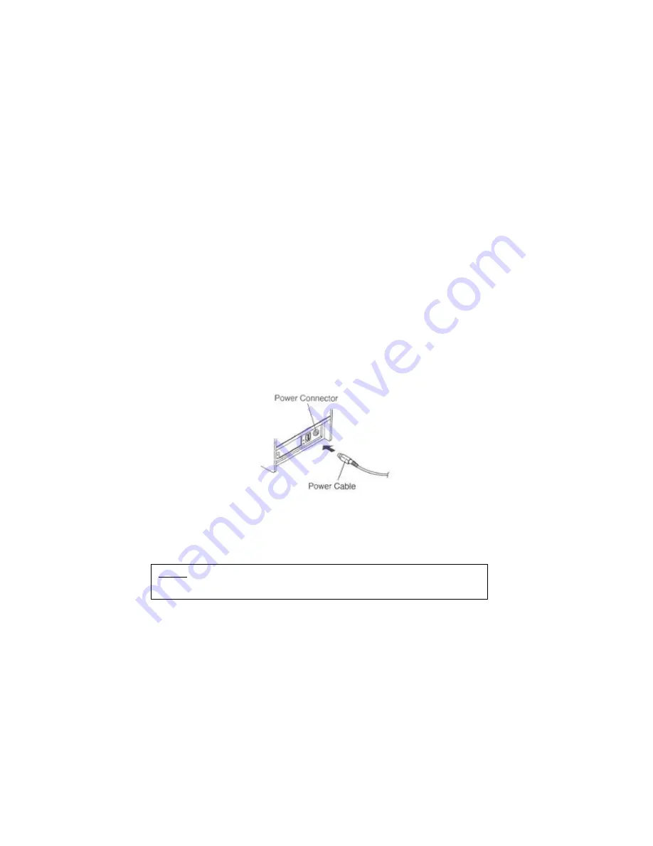
1-5. Connecting the Power Supply 


CAUTIONS: 

 When connecting or disconnecting the power supply from the printer, make sure that     

    the power supply is not plugged into an electrical outlet. Otherwise you may damage  

    the power supply or the printer. 


 If the power supply’s rated voltage and your outlet’s voltage do not match, contact your  

 dealer for assistance. Do not plug in the power cord. Otherwise, you may damage the  

 power supply or the printer. 


 1. Make sure that the printer’s power switch is turned off, and the power supply’s power  

  cord is unplugged from the electrical outlet. 


 2. Check the label on the power supply to make sure that the voltage required by the  

  power supply matches that of your electrical outlet. 


 3. Plug in the power supply’s cable as shown below. Notice that the flat side of the plug  

 faces down. 


Notes : To remove the DC cable connector, make sure that the power supply’s power  

  cord is unplugged; then grasp the connector at the arrow and pull it straight out. 

Содержание SRP - 350

Страница 1: ...Operator s Manual All specifications are subjected to change without notice SRP 350 RECEIPT PRINTER ...

Страница 2: ...onductor devices are easily damaged by static electricity You should turn the printer OFF before you connect or remove the cables on the rear side in order to guard the printer against the static electricity If the printer is damaged by the static electricity you should turn the printer OFF INTRODUCTION The SRP 350 SRP 350S SRP 350P and SRP 350U Roll Printer are designed for use with electronic in...

Страница 3: ... THE POWER SUPPLY 7 1 6 INSTALLING OR REPLACING THE PAPER ROLL 8 1 7 ADJUSTMENTS AND SETTINGS 10 1 8 USING THE PRINTER 11 CHAPTER 2 HEXADECIMAL DUMPING 14 CHAPTER 3 THE SELF TEST 15 CHAPTER 4 CODE TABLE 16 CHAPTER 5 CONTROL COMMANDS LIST 24 APPENDIX 27 A STAR MODE COMMAND SUMMARY 27 B CONNECTORS 30 Interface Connector 31 Drawer Connector 34 C NOTES 34 D SPECIFICATION 35 ...

Страница 4: ...4 Chapter 1 Setting Up the Printer 1 1 Unpacking Your printer box should include these items If any items are damaged or missing please contact your dealer for assistance ...

Страница 5: ...an connect up the three cables to the printer They all connect to the connector panel on the back of the printer which is shown below Notes Before connecting any of the cables make sure that both the printer and the host are turned off ...

Страница 6: ...he cable to the computer 1 4 Connecting the Drawer WARNING Use a drawer that matches the printer specification Using an improper drawer may damage the drawer as well as the printer CAUTION Do not connect a telephone line to the drawer kick out connector otherwise the printer and the telephone line may be damaged Plug the drawer cable into the drawer kick out connector on the back of the printer ne...

Страница 7: ...therwise you may damage the power supply or the printer 1 Make sure that the printer s power switch is turned off and the power supply s power cord is unplugged from the electrical outlet 2 Check the label on the power supply to make sure that the voltage required by the power supply matches that of your electrical outlet 3 Plug in the power supply s cable as shown below Notice that the flat side ...

Страница 8: ...er open button 3 Remove the used paper roll core if there is one 4 Insert the paper roll as shown Notes Be sure to use paper rolls that meet the specifications Do not use paper rolls that have the paper glued to the core because the printer cannot detect the paper end correctly Notes Do not open the print cover while the printer is operating This may damage the printer ...

Страница 9: ...rection that the paper comes off the roll 6 Pull out a small amount of paper as shown Then close the cover 7 Tear off the paper as shown Notes When closing the cover press the center of printer cover firmly to prevent Paper miss loading ...

Страница 10: ...ge communication settings such as handshaking and parity check as well as print density The SRP 350 also has a near end sensor for the paper This can give you a warning when the paper is almost out If you find that there is not enough paper remaining on the roll when the near end detector is triggered you can change the near end sensor setting Rotate the near end sensor tab at front or rear positi...

Страница 11: ...feed paper continuously Panel lights POWER The POWER light is on whenever the printer is on ERROR This indicates an error PAPER OUT This light indicates the near end of the paper roll Install a new paper roll and the printer will continue printing When the light blinks it indicates the self test printing standby state or macro execution standby state when the macro execution command is used ...

Страница 12: ...EN ODD OFF 7 ON 8 Baud rate selection Refer to the Following Table OFF Baud rate selection Transmission speed SW 7 SW 8 2400 baud ON ON 4800 baud OFF ON 9600 baud ON OFF 19200 baud OFF OFF Dip Switch Set 2 Functions SW FUNCTION ON OFF DEFAULT 1 Emulation STAR EPSON OFF 2 Reserved 3 Reserved 4 Reserved 5 OFF 6 Select Print Density Refer to the Following Table OFF 7 Reserved 8 Reserved Print Density...

Страница 13: ...ed OFF 5 Reserved OFF 6 Reserved OFF 7 Reserved OFF 8 Reserved OFF Dip Switch Set 2 Functions SW FUNCTION ON OFF DEFAULT 1 Emulation STAR EPSON OFF 2 Reserved 3 Reserved 4 Reserved 5 OFF 6 Select Print Density Refer to the Following Table OFF 7 Reserved 8 Reserved Print Density Print Density SW 5 SW 6 1 Light ON ON 2 OFF OFF 3 ON OFF 4 Dark OFF ON ...

Страница 14: ...down the FEED button 3 Close the cover then the printer enters the hexadecimal dump mode 4 Run any software program that sends data to the printer The printer will print all the codes it receives in a two column format The first column contains the hexadecimal codes and the second column gives the ASCII characters that corresponds to the codes 1B 21 00 1B 26 02 40 40 40 40 02 0D 1B 44 0A 14 1E 28 ...

Страница 15: ... current printer status which provides the control ROM version and the DIP switch setting 4 After printing the current printer status self test printing will print the following and pause The PAPER LED light blinks Self test printing Please press the FEED button 5 Press the FEED button to continue printing The printer prints a pattern using the built in character set 6 The self test automatically ...

Страница 16: ...e tables To find the character corresponding to a hexadecimal number count across the top of the table for the left digit and count down the left column of the table for the right digit For example 4A J Page 0 PC437 USA Standard Europe International Character Set USA ...

Страница 17: ...17 Page 2 PC850 Multilingual ...

Страница 18: ...18 Page 3 PC860 Portuguese ...

Страница 19: ...19 Page 4 PC 863 Canadian French ...

Страница 20: ...20 Page 5 PC 865 Nordic ...

Страница 21: ...21 Page 19 PC 858 Euro ...

Страница 22: ...22 Page 255 Space Page ...

Страница 23: ...23 International Character Set ...

Страница 24: ...c2 Define user defined characters ESC m nL nH 1B 2A m nL nH Select bit image mode ESC n 1B 2D n Turn underline mode on off ESC 2 1B 32 Select default line spacing ESC 3 n 1B 33 n Set line spacing ESC n 1B 3D n Set peripheral device ESC n 1B 3F n Cancel user defined characters ESC 1B 40 Initialize printer ESC D n1 nK 1B 44 00 Set horizontal tab position ESC E n 1B 45 n Turn emphasized mode on off E...

Страница 25: ... nL nH 1D 24 nL nH Set absolute vertical print position in page mode GS x y 1D 2A x y Define downloaded bit image GS m 1D 2F n Print downloaded bit image GS 1D 3A Start end macro definition GS B n 1D 42 n Turn white black reverse printing mode on off GS H n 1D 48 n Select printing position of HRI characters GS I n 1D 49 n Transmit printer ID GS L nL nH 1D 4C nL nH Set left margin GS P x y 1D 50 x ...

Страница 26: ... Control codes Hexadecimal codes Function GS k m NUL GS k m n 1D 6B m NUL 1D 6B m n Print bar code GS r n 1D 72 n Transmit status GS v 0 m 1D 76 30 Print raster bit image GS w n 1D 77 n Set bar code width ...

Страница 27: ... character width DC4 14 Resets the printing magnified in character width ESC W n 1B 57 n Sets the magnification rate in character width ESC SO 1B 0E Sets the printing magnified double in character height ESC DC4 1B 14 Resets the printing magnified in character height ESC h n 1B 68 n Sets the magnification rate in character height ESC 1 ESC 1 1B 2D 31 1B 2D 01 Select underlining ESC _ 1 ESC _ 1 1B ...

Страница 28: ...normal density graphics ESC L n 0 m1 m2 1B 4C n1 n2 m1 m2 Print high density graphics ESC k n 0 d1 1B 6B n 00 d1 Print fine density graphics ESC X n1 n2 1B 58 n1 n2 Print fine density graphics ESC FS p n m 1B 1C 70 n m Print NV bit image ESC 1 1 n m1 m2 m48 1B 26 31 31 n m1 m2 m48 ESC 1 1 n m1 m2 m48 1B 26 01 01 n m1 m2 m48 Define download character ESC 1 0 n 1B 26 31 30 n ESC 1 0 n 1B 26 01 00 n ...

Страница 29: ... last line initialize printer immediately DC3 13 Deselect printer DC1 11 Set select mode RS 1E Beep the buzzer ESC 1B 40 Initialize printer ENQ 05 Inquiry Status inquiry EOT 04 Near end status inquiry ESC LF NUL 1B 3F 0A 00 Reset printer hardware Perform test print ESC 8 n1 n2 1B 38 n1 n2 Registers a logo pattern ESC 9 n1 n2 1B 39 n1 n2 Prints a logo pattern ...

Страница 30: ...30 B Connectors SRP 350 SRP 350S Connector Serial Interface SRP 350P Connector Parallel Interface SRP 350U Connector USB Interface ...

Страница 31: ...eceive Data 6 DSR Input Data Set Ready 7 SG Signal Ground 20 DTR Output Data Terminal Ready Serial Interface RS 485 Pin No Signal Name Direction Function 1 FGND Frame Ground 2 SD2 Output 3 SD1 Output Send Data 4 RD2 Input 5 RD1 Input Receive Data 7 SGND Signal Ground 8 9 DR2 DR1 Output Same as DTR RS 232 10 11 CS2 CS1 Input Same as DSR RS 232 ...

Страница 32: ...ter Data 6 Data 6 9 Host Printer Data 7 MSB Data 7 MSB 10 Printer nAck PtrClk PtrClk 11 Printer Busy PtrBusy Data3 7 PtrBusy 12 Printer Perror AckDataReq Data2 6 AckDataReq 13 Printer Select Xflag Data1 5 Xflag 14 Host nAutoFd HostBusy HostBusy 15 NC NC NC 16 GND GND GND 17 FG FG FG 18 Printer Logic H Logic H Logic H 19 30 GND GND GND 31 Host nInit nInit nInit 32 Printer nFault nDataAvail Data0 4 ...

Страница 33: ...33 USB Interface Pin No Signal Name Assignment Color Function Shell Shield Drain Wire Frame Ground 1 VBUS Red Host Power 2 D White Data Line D 3 D Green Data Line D 4 GND Black Signal Ground ...

Страница 34: ...ty In this case clean the printer as follows 1 Open the printer cover and remove the paper if exists 2 Clean the print head with a cotton swab moistened with alcohol solvent 3 Clean the platen roller and paper end sensor with cotton swab moistened with water 4 Insert a paper roll and close the printer cover The remained amount of paper detected by paper near end sensor varies with the diameter of ...

Страница 35: ... and the combination of control commands Input voltage 120 230 VAC Frequency 50 60 Hz Supply voltage Output voltage 24 VDC Temperature 5 45 o C Operating 10 50 o C Storage Environmental conditions Humidity 30 80 RH Operating 10 90 RH Storage Except for paper Mechanism Head 15 000 000 lines 1x10⁸ pulse Approximately 100 Km LIFE Auto Cutter 1 000 000 Cut MCBF Mechanism 37 000 000 lines These values ...

Отзывы: