3) Door open
when door is open, the related display shows an actual temperature.
3-1) Display range of freezer is -35
˚C
~ 30
˚C
and refrigerator is -9
˚C
~9
˚C
.
3-2) If freezer inner temperature is above 0
˚C
for 10 minute, the display of the selected temp.
will blink.
3-3) If refrigerator inner temperature is above 15
˚C
for 10 minute, the display of the selected
temp. will blink.
3-4) When door is open, 1
˚C
will increase after delay time from the display before door
opens. When door close, 1
˚C
will decrease after delay time if there is a change in inner
temperature. Temperature will reach up to presently selected notch.
4) Defrost Display function
4-1) If defrost starts both freezer and refrigerator display the selected temperature. So it will
not blink for 2 hours even if it sensed faulty in inner temperature, after 2 hours it will
decide to blink or not.
❈
code for temperature might change due to after the progress in development in products
NO
1
2
3
4
5
6
7
8
9
10
11
12
13
DA41-00099A
DA41-00099B
DA41-00102A
DA26-30111H
DA26-30111F
DA26-30111C
DA32-00006C
DA32-00006C
DA32-10109H
DA32-10105A
DA41-00013B
DA41-20160A
DA41-20148A
PBA MAIN
PBA MAIN
PBAPANEL
DC TRANS
F, R DEF SENSOR
F, R DEF SENSOR
R SENSOR
F SENSOR
INVERTER PCB
W2 PJT
W2 PJT
W2 PJT
220~240V/50, 60Hz
105V/50,60Hz
127V/50,60Hz
PX-41C
PX-41C
PX-41C
PX-41C
220~240V/50,60Hz
127V/50,60Hz
105~115V/50,60Hz
1
1
1
1
1
1
1
1
1
1
1
1
1
Different
according to the
source of power
AHAM OPTION
Different
according to the
source of power
SPEC
Q’ty
Remark
CODE NO
ITEM
(PCB Part List)
State of COMP cooling fan according to the ambient temperature (When COMP. is re-started)
- always OFF COMP cooling fan when ambient temperature is below 5˚C.
- COMP cooling fan always switch ON after 9 minute when ambient temperature is 6˚C~10˚C.
- COMP cooling fan always switch ON after 6 minute when ambient temperature is 11˚C~15˚C.
- COMP cooling fan always switch ON after 3 minute when ambient temperature is 16˚C~21˚C.
- COMP cooling fan always switch ON when ambient temperature is over 21˚C.
Reference
18
Содержание SR-L627EV
Страница 5: ...5 4 Circuit Diagram 4 1 230V 240V 50Hz 220v 50Hz 60Hz 127V 60Hz 115V 60Hz ...
Страница 10: ...5 4 Cool Air Circulation 10 ...
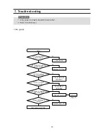
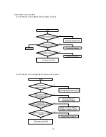
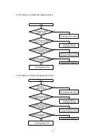
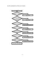
Страница 27: ...2 3 Problem in refrigerator defrost sensor 2 4 Problem in freezer temperature sensor 27 ...
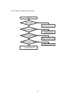
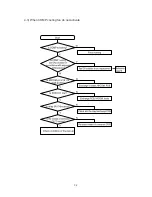
Страница 28: ...2 5 Problem in freezer defrost sensor 28 ...
Страница 31: ...4 2 When refrigerator fan R fan do not activate 31 ...
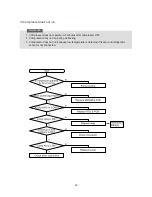
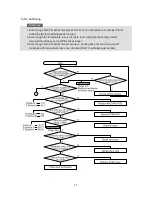
Страница 32: ...4 3 When COMP cooling fan do not activate 32 ...
Страница 34: ...34 ...
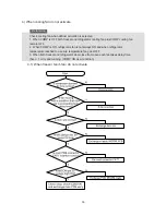
Страница 36: ...6 2 If Beep sounds continuously 6 3 When original panel PCB do not activate 36 ...
Страница 37: ...6 4 When buttons of panel PCB is not selected 37 ...
Страница 43: ...9 Exploed View 9 1 Freezer room 43 ...
Страница 45: ...LAMP FLUORESCENT 9 2 Refrigeration room 45 ...
Страница 48: ...SR L627EV SR L677EV 9 3 Door parts 48 ...
Страница 51: ...9 4 Cabinet parts unit 51 ...
Страница 56: ...56 6 Remove the housing of wires ...
Страница 63: ...63 11 PCB Circuit Diagram ...
Страница 66: ...66 ...
Страница 67: ...67 ...
Страница 68: ...68 ...
Страница 69: ...69 ...
Страница 70: ...70 ...
Страница 71: ...71 ...
Страница 72: ...72 ...
Страница 73: ...73 ...
Страница 74: ...74 ...
Страница 75: ...75 ...
Страница 76: ...76 ...
Страница 77: ...77 ...
Страница 78: ...78 ...
Страница 79: ...79 ...
Страница 80: ...80 ...
Страница 81: ... Samsung Electronics Co Ltd November 2001 Printed in Korea Code No DA68 01130A REV 0 0 ...


