- 6 -
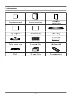
Registration card
Owner’s manual
Installation
Instructions
Top template
Wall template
Glass tray
Roller guide ring
Charcoal filter
Hardware-kit
Shelf
Grease filters
Exhaust adaptor
3-3 Accessary
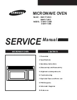
Страница 1: ...recaution 2 Specifications 3 Operating Instructions 4 Disassembly and Reassembly 5 Alignment and Adjustments 6 Troubleshooting 7 Exploded Views and Parts List 8 PCB Diagrams 9 Schematic Diagrams 10 Reference BASIC SMH7174WD SMH7174BD MODEL SMH7174WE SMH7174BE ...
Страница 2: ...rol Circuit Board 13 4 8 1 Removal of Control Box 13 4 8 2 Removal of P C B Assembly 13 5 Alignment and Adjustments 14 5 1 High Voltage Transformer 14 5 2 Low Voltage Transformer 14 5 3 Magnetron 14 5 4 High Voltage Capacitor 15 5 5 High Voltage Diode 15 5 6 Main Relay and Power Control Relay 15 5 7 Adjustment of Primary Switch Door Sensing Switch and Monitor Switch 15 5 8 Vent Exhaust Blower Moto...
Страница 3: ...Parts List 30 7 4 Standard Parts List 31 8 P C B Diagrams 32 8 1 P C B Diagrams 32 8 2 P C B Parts List 33 9 Schematic Diagrams 35 9 1 Schematic Diagrams 35 10 Reference 36 10 1 Model name standard 36 10 2 Customer inquiry cases and countermeasures 37 ...
Страница 4: ...ction within the microwave generating compartments check the magnetron wave guide or transmission line and cavity for proper alignment integrity and connections d Any defective or misadjusted components in the interlock monitor door seal and microwave generation and transmission systems shall be repaired replaced or adjusted by procedures described in this manual before the oven is released to the...
Страница 5: ...ches while repairing an MWO 11 To avoid any possible radiation hazard replace parts in accordance with the wiring diagram Also use only the exact replacements for the following parts Primary and secondary interlock switches interlock monitor switch 12 If the fuse is blown by the Interlock Monitor Switch Replace all of the following at the same time Primary door sensing switch and power relay as we...
Страница 6: ...and discharge the high voltage capacitor See Figure 1 1 2 The high voltage capacitor remains charged about 30 seconds after disconnection Short the negative terminal of the high voltage capacitor to to the oven chassis Use a screwdriver 3 High voltage is maintained within specified limits by close tolerance safety related components and adjustments If the high voltage exceeds the specified limits ch...
Страница 7: ...E DIMENSIONS OVEN CAVITY DIMENSIONS SHIPPING DIMENSIONS NET WEIGHT SHIPPING WEIGHT 99 MINUTES 99 SECONDS 120V 60Hz MICROWAVE 1 650W FROM 100 TO 1100W 10 LEVEL POWER IEC 705 TEST PROCEDURE 2 450MHz OM75P 10 ERHN COOLING FAN MOTOR 297 8 W x 1515 16 H x 1511 32 D mm 207 8 W x 109 32 H x 141 32 D mm 333 8 W x 1915 16 H x 1913 32 D mm 58 4 lbs 64 4 lbs ...
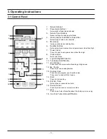
Страница 8: ...er than high 7 Power Level Press this pad to set a power level other than high 8 Clock am pm Sets current time 9 Light On Night Off Button 10 Turntable On Off Button 11 One Minute Press once for every minute of cooking at High power 12 My Choice Press to set non cooking feature 13 Custom Cook Press twice to program your favorite recipe Press once to cook with that recipe 14 Start Press to start co...
Страница 9: ... 5 Door Door Latches Handle Ventilation Holes Oven Light Safety Interlock Holes Control Panel Intake Holes Glass Tray Guide Roller 398mm 758 9mm 417 25mm 405mm 3 2 Features External Views ...
Страница 10: ... 6 Registration card Owner s manual Installation Instructions Top template Wall template Glass tray Roller guide ring Charcoal filter Hardware kit Shelf Grease filters Exhaust adaptor 3 3 Accessary ...
Страница 11: ...talled to cabinet arrangements such as an island or peninsula It must be mounted to both a top cabinet and wall VENT BLOWER The vent or exhaust blower is located at the top of the oven It is shipped for vertical exhaust but can be changed to rear exhaust or recirculating See installation instrustions on how to change and or blower section on how to remove COOKTOP LIGHTS One 40 watt screw base inca...
Страница 12: ...cannot turn it The fan will automatically turn off when the internal parts are cool If may stay on for 30 minutes or more after the cooktop and microwave controls are turned off GRILLE REMOVAL The top full width grille is removable for service to some components such as oven light cavity T C O vent motor capacitor and fuse TO REMOVE GRILLE 1 Disconnect oven power 2 Remove screws 2 from grille oute...
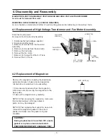
Страница 13: ...lly NOTE1 When removing the magnetron make sure that it antenna does not hit any adjacent parts or it may be damaged NOTE2 When replacing the magnetron be sure to remount the magnetron gasket in the correct position and make sure the gasket is in good condition CAUTION During replacement be certain R F anode gasket is in place around anode stub PERFORM MICROWAVE LEAKAGE TEST 4 1 Replacement of Hig...
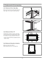
Страница 14: ...embly 4 3 2 Removal of Door E Following the procedure as shown in the figure insert and bend a thin metal plate between Door E and Door A until you hear the tick sound Insertion depth of the thin metal plate should be 0 5mm or less 4 3 3 Removal of Key Door Spring Remove pin hinge from Door E Detach spring from Door E and key door Door A Door C Door E ...
Страница 15: ...AIN FUSE 1 When 20A fuse blows out by the operation of interlock monitor switch failure replace the primary interlock switch door sensing switch interlock monitor switch and power relay 2 When the above 3 switches operate properly check if any other part such as the control circuit board blower motor or high voltage transformer is defective H V TRANS FUSE 1 When 20 Amp fuse is blown due to operati...
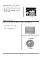
Страница 16: ... motor screws 1 and lift up stirrer motor after turn left STIRRER MOTOR The stirrer is located on the upper side of the cavity The oven uses a top feed wave guide 1 Disconnect power and open the door 2 Remove the clip and turn the stirrer cover left 3 Remove stirrer cover and the stirrer will come with it 4 Replace the clip if the clip head broken CLIP COVER STIRRER COVER STIRRER STIRRER ASSEMBLY ...
Страница 17: ...t the connectors from the control circuit board 4 8 2 Removal of P C B Assembly 1 Pull the lever end of the plastic fastener and remove the Flexible Printed Circuit FPC of mem brane panel 2 Remove screws 3 securing the control circuit board 3 Lift up the control circuit board from the Ass y con trol box 4 When reconnecting the FPC connector make sure that the holes on the connector are properly en...
Страница 18: ...dicate one ohm or less 4 A continuity check between each filament terminal and magnetron case should read open Cooling Fins Magnetron Antenna Gasket Plate 5 3 Magnetron 5 2 Low Voltage Transformer 5 1 High Voltage Transformer 1 Remove connectors from the transformer terminals and check continuity 2 Normal resistance readings are as follows SHV U1870B Secondary Filament Primary 79Ω 10 Shows Continui...
Страница 19: ...tch Body to the oven assem bly adjust the Latch Body by moving it so that the oven door will not have any play in it Check for play in the door by pulling the door assembly Make sure that the latch keys move smoothly after adjustment is completed Completely tighten the screws holding the Latch Body to the oven assembly 4 Reconnect to Monitor switch and check the continu ity of the monitor circuit ...
Страница 20: ...but would be much slower TO TEST THE CAPACITOR 1 Remove grille discharge capacitor and disconnect one capacitor lead 2 Make appropriate capacitor check with analog meter needle should rise then fall cap is charging then discharging TO TEST BLOWER WINDINGS 1 Disconnect power and remove grille 2 Open control panel and discharfe capacitor 3 Disconnent two wires to run capacitor Continuity test across...
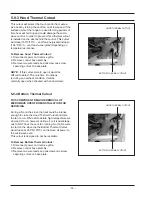
Страница 21: ... the oven cavity beside exhaust duct with a temperature rating of 248 F 120 C and is non resetable The cutout is tightly held to the top of the oven cavity by duct upper 5 9 2 Replacement of Flame Sensor Disconnect oven power Remove Grille Panel outer 1 Remove screws 3 securing the duct upper 2 Loft up the duct upper from the cavity 3 Disconnect two wire leads 4 Press the top of the thermal cutout...
Страница 22: ...t The only time it functions is during an overheat condition It will be normally open when checked with an ohmmeter 5 9 4 Bottom Thermal Cutout THIS COMPONENT REQUIRE REMOVAL OF MICROWAVE OVEN FROM INSTALLATION FOR SERVICING During a fire on the stove the heat could be intense enough to close the Hood Thermal Cutout and force the fan to run While at moderate high temperature we do want it to run ho...
Страница 23: ...on uses a special humidity sensor which detects humidity during the cooking process Before conducting either of the sensor tests below ensure the unit is plugged into a wall outlet for at least 5 minutes If already plugged in proceed The sensor is a plug in device located in the vent area at the top left hand corner of the cavity behind the grille To Service 1 Disconnect power and remove grille 2 ...
Страница 24: ...water again with the thermometer and measure the temperature T2 5 Subtract T1 from T2 This will give you the water temperature rise T 6 The output power is obtained by the following formula Output Power 4 187 x 1000 x T 0 55xMcx T2 T0 41 Heating Time sec 38 Counting Time sec 4 187 Coefficient for Water 1000 Water cc T Temperature Rise T2 T1 To Room Temperature Mc Cylindrical borosilicate glass weig...
Страница 25: ...oor keep the probe perpendicular to the areas making sure that the probe end at the base of the cone does not get closer than 5cm to any metal If it gets closer than 5cm erroneous readings may result 5 Measured leakage must be less than 4mW cm2 after repair or adjustment Maximum allowable leakage is 5mW cm2 4mW cm2 is used to allow for measurement and meter accuracy 1 Do not exceed the limited sca...
Страница 26: ...mer starts countdown but no microwave oscillation No heat while oven lamp and fan motor turn on 1 Off alignment of latch switches 2 Open or loose connection of high voltage circuit especially magnetron filament circuit NOTE Large contact resistance will bring lower magnetron filament voltage and cause magnetron to lower output and or intermittent oscillation 3 Defective high voltage components H V T...
Страница 27: ...e turntable motor Replace turntable motor Oven stops operation during cooking 1 Open or loose wiring of primary interlock switch 2 Operation of thermal cutout Magnetron Adjust door and latch switches Sparks 1 Metallic ware or cooking dishes touching on the oven wall 2 Ceramic ware trimmed with gold or silver powder also causes sparks Inform the customer Do not use any type of cookware with metalli...
Страница 28: ...or respectively 4 For unusual cases errors can be indicated in letters after discussion in advance ex Key Short Error SE 5 Error code not mentioned below should be discussed in advance and approved by P L and numbered reported to relevant departments 6 This numbering rule has been applied to models to have been developed since January 1 2005 But GE or Customize model are excluded E 1 1 DEVICE 0 Ot...
Страница 29: ...D in first 3 minutes after cooking by heater starts Error Code Gas Sensor Error Case E 1X E 31 Open When value of HEX is above FF for 5 seconds E 32 Short E 33 In case the initial value of HEX is under 14 for 30 seconds while a weight sensor in operation E 34 In case the initial value of K calculated by a weight sensor is above and under 28 as value of HEX E 35 In case the value of A is as a weight...
Страница 30: ...ter SE Key Short Error 10 seconds E 01 The door opens in case the door should not be opened E 02 Cooking Time Setting Over Error MWO E 03 Cooking Time Setting Over Error Grill E 04 Cooking Time Setting Over Error Convection E 05 Cooking Time Setting Over Error Combination E 06 It fails to sense that the swing heater has stopped for 20 seconds during cooking E 08 In case function of MWO starts with...
Страница 31: ... U005 M036 P030 P124 P122 U003 P016 P015 P034 P013 P014 P001 P039 C089 M219 P097 P032 M015 M001 M035 M029 M040 M039 M041 M206 P059 M050 M167 B002 B001 B013 U004 U003 U007 U001 P122 P123 M038 P121 M048 M155 M036 P012 P006 P125 P007 M024 M060 P090 P087 P088 P091 P089 D002 C004 D049 C082 C005 C009 C003 C089 D005 D011 D060 D004 D006 D019 D020 D026 C001 H018 D024 D016 P156 C073 R066 ...
Страница 32: ...1 SA 1 1 M087 DE71 60121A COVER STIRRER PP T2 0 W7 L198 85G 1 SA 1 1 T001 DE74 20002A TRAY COOKING GLASS T6 1 SA 1 1 P012 DE92 90242A ASSY HOOD DAMPER JVM 250BL OTR4 1 SA 1 2 P013 DE71 60051A COVER DAMPER FESN5 T0 22 W68 L248 4 1 SA 1 2 P014 DE72 40022A DAMPER MAIN SECC W28 L650 OTR4 T0 1 SA 1 1 M060 DE92 90505E ASSY HARD WARE SMH7175 1 SA 1 2 P087 DE60 10111A SCREW LAG MSWR W1 4X50 1 SA 1 2 P088 ...
Страница 33: ...60HZ 1 SA 1 2 H018 DE31 90051A BLADE FAN P P T D130 1 SA 1 2 P109 DE63 00141A COVER MOTOR SMH7175 PP FB53 T2 5 1 SA 1 2 M017 DE96 00400B ASSY NOISE FILTER SN UF12B 250V20A OTR10 1 SA 1 1 P034 DE97 00366C ASSY DUCT UPPER SMH7175 HUMIDITY SENSOR 1 SA 1 2 P122 DE47 20059A THERMOSTAT PW 2N 8XV 125V15A V 120 0 23 1 SA 1 2 P030 DE59 50002A CAPACITOR MOTOR SH M 10UF 220V10UF DMB 1 SA 1 2 P097 DE97 00371B...
Страница 34: ...0 WHT 1 SA WE 1 3 D026 DE63 00139A COVER HANDLE SMH7175 PC T2 0 BLK 1 SA BE 1 3 D019 DE64 00761B HANDLE DOOR SMH7175 PC T2 0 WHT 1 SA WE 1 3 D019 DE64 00761A HANDLE DOOR SMH7175 PC T2 0 BLK 1 SA BE 1 1 C082 DE94 00933P ASSY CONTROL BOX SMH7174WE XAA WHITE V 1 SA WE 1 1 C082 DE94 00933N ASSY CONTROL BOX SMH7174BE XAA BLACK V 1 SA BE 1 2 C089 DE39 40673A WIRE HARNESS H 120V60HZ OTR6 ALL MODEL G 1 SA...
Страница 35: ...4 L12 NI PLT MSWR 2 SA GRILLE 1 1 6002 001174 SCREW TAPPING FH 2S M4 L12 NI PLT MSWR 6 SA P OUTER 1 1 6002 001320 SCREW TAPPING TH 2S M4 L8 PASS STS304 5 SNA BASE BOTTOM 1 1 6002 001320 SCREW TAPPING TH 2S M4 L8 PASS STS304 4 SNA P OUTER 1 1 6006 001170 SCREW TAPPING TH WT TC M4 L10 ZPC YEL SWRCH18A 1 SNA C BOX EARTH 1 1 6006 001170 SCREW TAPPING TH WT TC M4 L10 ZPC YEL SWRCH18A 1 SNA HUMIDITY SEN...
Страница 36: ... R31 47K D23 1N4148M 2K R41 5V R40 2K 2K R13 C10 100nF 24V 47K R34 100nF C15 R30 180 330 R29 LVT1 SLV 5574U 47K TR05 KRC246M KRC246M TR04 R33 4 7uF C12 5V R10 2 2K 470 R02 5V 5V 1K R19 C13 10nF F1 1N4148M D05 FTR F3AA024E RY02 UZ5 1BSB ZD05 2K R39 D09 R38 2K 1N4148M D10 1N4148M R01 470 PTC1 270M D08 1N4148M D15 1T4 ZNR1 10D471 R22 470 RY09 FTR F3AA024E 100K R27 KRC246M TR15 R11 2K TR14 KRC246M RY0...
Страница 37: ... NPN 400MW 2 2K 10KOHM 1 SNA TR17 1 4 1201 001125 IC OP AMP 75S01 SOP 5P 63MIL SINGLE 100D 1 SA IC04 1 4 1203 001238 IC POSI ADJUST REG 78L15 TO 92 3P PLA 1 SNA IC02 1 4 1404 000230 THERMISTOR PTC 27OHM 20 1 SNA PTC1 1 4 1405 000001 VARISTOR 470V 1250A 14x7 5mm TP 1 SNA ZNR1 1 4 2001 000009 R CARBON 20KOHM 5 1 8W AA TP 1 8X3 2MM 1 SNA R12 1 4 2001 000062 R CARBON 470OHM 5 1 4W AA TP 2 4X6 4MM 1 SN...
Страница 38: ...401 002216 C AL 2200uF 20 35V GP TP 16x25 7 5 1 SNA C01 1 4 DE13 20009A IC KA7533 DIP 1 SNA IC03 1 4 2004 005092 R METAL 348KOHM 1 1 8W AA TP 1 8X3 2MM 1 SNA R30 1 4 2001 000780 R CARBON 470OHM 5 1 8W AA TP 1 8X3 2MM 1 SNA R02 1 4 2004 004255 R METAL 3 32KOHM 1 1 8W AA TP 1 68X3 81 1 SNA R25 1 4 2004 000517 R METAL 200KOHM 1 1 8W AA TP 1 8X3 2M 1 SNA R26 1 3 DE61 90164A HOLDER DIGITRON BLK NYLON 6...
Страница 39: ... 35 9 Wiring Diagrams 9 1 Wiring Diagrams This Document can not be used without Samsung s authorization ...
Страница 40: ... 36 9 1 Wiring Diagrams continued ...
Страница 41: ...ON C RC USA RV CONVECTION BUILT IN B RB USA RV BUILT IN USA Junior SJ SJ USA Junior MWO USA OTR SM SOLO H SMH USA OTR SOLO CONVECTION V SMV USA OTR CONVECTION EUROPE Ep oxy Cavity M SOLO 1 M1 EUROPE SOLO EPOXY CAVITY GRILL 2 M2 EUROPE GRILL EPOXY CAVITY EUROPE Ce ramic Enamel CE SOLO 1 CE1 EUROPE SOLO CERAMIC ENAMEL GRILL 2 CE2 EUROPE GRILL CERAMIC ENAMEL EUROPE Quartz GRILL G2 G2 EUROPE Quartz GR...
Страница 42: ...IUM LOW This function is used to cook the food slowly Close the door completely Press the Cancel but ton Press the Start button Contact the nearest Samsung after sales service cen ter Ground Ground problem may happen when the oven is placed in a humid area and the over is not grounded Ground is not provided by an extended electric outlet If the oven is placed in a humid area buy an electric wire i...
Страница 43: ...such as herbal remedies are not removed Error Errors are classified into the case which is out of order and the case which is not out of order Clean the inside of the oven Remove strange smell through the Deodorant button If the strange smell still remains place a piece of lemon on the turntable and operate the oven for 5 minutes by pressing the Deodorant button However the smells produced from the...
Страница 44: ...ual is a property of Samsung Electronics Co Ltd Any unauthorized use of Manual can be punished under applicable International and or domestic law Samsung Electronics Co Ltd Aug 2005 Printed in Korea Code No DE68 03971A ...