background image

9-2

Samsung Electronics

MEMO

Содержание SM0-150TPV

Страница 1: ...10TPV SMO 150TPV COLOR MONITOR CONTENTS Precautions Specifications Alignment and Adjustments Troubleshooting Exploded Views and Parts List Electrical Parts List Block Diagrams PCB Diagram Wiring Diagram Schematic Diagrams 1 2 3 4 5 6 7 8 9 10 ...

Страница 2: ...andle brackets metal cabinets screwheads and control shafts The current measured should not exceed 0 5 milliamp Reverse the power plug prongs in the AC outlet and repeat the test Fig 1 1 AC Leakage Test 6 Jack Cold Check With the unit s AC plug disconnected from the AC source connect an electrical jumper across the two AC prongs Connect one lead of the ohmmeter to an AC prong Connect the other lea...

Страница 3: ... wiring that appear to have overheated or that are otherwise damaged should be replaced with parts that meet the original specifications Always determine the cause of damage or overheat ing and correct any potential hazards 15 Observe the original lead dress especially near the following areas sharp edges and especially the AC and high voltage power supplies Always inspect for pinched out of place...

Страница 4: ...g and accessible conductive parts examples metal panels input terminals and earphone jacks 6 Insulation Checking Procedure Disconnect the power cord from the AC source and turn the power switch ON Connect an insulation resistance meter 500V to the blades of the AC plug The insulation resistance between each blade of the AC plug and accessible conductive parts see above should be greater than 1 meg...

Страница 5: ...n anti static solder removal device Many solder removal devices are not rated as anti static these can accumulate sufficient electrical charge to damage ESDs 7 Do not remove a replacement ESD from its protective package until you are ready to install it Most replacement ESDs are packaged with leads that are electrically shorted together by conductive foam aluminum foil or other conductive material...

Страница 6: ... Line Up Table 2 1 IC Line Up Loc No IC201S IC301 IC501 IC601 IC801S IC902 PC801S IC602 IC202 203 IC804 IC805 IC806 Description TDA9380PS N211 OTP English China VERTICAL OUTPUT RGB DRIVE AMP SOUND AMP POWER IC STR EEPROM PHOTO COUPLER IC CMOS LOGIC IC I O SUPORT CHIP IC POSI FIXED REG IC SWITCH REG FET SILICON Specification L_DIYP06_001 LA7845 TDA6107Q TDA7267 STR F6656 24C04 PS2561 HCF4053 PCF857...

Страница 7: ...ics 2 3 Semiconductor Basic Diagrams ELECTROLYTIC CONDENSER IC DIODE LPM900W2 Pin 64 HCF4053 Pin 16 IC TRANSISTOR Fig 2 1 Semiconductor Base Diagrams LA7840 TDA6107Q KA7632 TRANSISTOR TRANSISTOR KSC5802 B C E E B C KSC815 Y KSA539 Y E C B KSC2331 Y ...

Страница 8: ... Fail Safe This adjustment must be the last step 2 If the EEPROM or CRT is replaced and set SC as 24 factory mod 3 2 Factory Service Mode 3 2 1 Procedure for the Adjustment Mode 1 This mode uses local key The Service Mode is activated by entering the following remote control sequence Menu 1 8 2 SET 2 The SERVICE FACTORY message will be displayed The Service Mode has four components ADJUST OPTION G...

Страница 9: ...eys in the following sequence Menu 1 8 2 SET 2 Press the Factory remote control keys in the following sequence Menu Factory ADJUST OPTION G2 ADJUST RESET Item SCT SBT BLR BLB RG GG BG VSL VS VA HS SC CDL STT AKB Initial 13 9 31 27 32 31 31 19 38 40 30 24 9 7 0 Item PDL NDL PSR NSR VOL SCL PWL PEK ACL FCO SCBT SSP MUS PSNS Initial 15 10 15 10 30 1 12 2 0 0 45 20 1 1 ...

Страница 10: ...Fix 5 Fix 10 Fix 10 Fix 1 Fix 12 Fix 2 Fix 0 Fix 0 Fix 45 Fix 1 0 Fix 1 Fix 1 Fix Remrk Sub contrast high light adjustment Sub brightness low light adjustment Black level offset R low light R adjustment Black level offset B low light B adjustment White point R high light R adjustment White point G high light 25 fixed White point B high light B adjustment Vertical slope Vertical shift Vertical ampl...

Страница 11: ...ST ADJUST OPTION G2 ADJUST RESET When the G2 ADJUST mode is entered SCREEN ADJUST will be shown as NG Adjust the Screen jack of FBT so that the value of SCREEN ADJUST can be shown as OK In this case AV1 must be in NO Signal ADJUST OPTION G2 ADJUST RESET 3 3 6 RESET The Reset Mode is used during User Menu Control Value inspection Function reset NO 1 2 3 ITEM Contrast Brightness Color Inital Value 5...

Страница 12: ...rnal degaussing after moving the Monitor should be unnecessary But the receiver must be properly degaussed upon installation The degaussing coil operates for about 1 second after the power is switched ON If the set has been moved or turned in a different direction disconnect its AC power for at least 30 minutes If the chassis or parts of the cabinet become magnetized poor color purity will result ...

Страница 13: ... Input a black and white signal 5 Fully demagnetize the receiver by applying an external degaussing coil 6 Turn the CONTRAST and BRIGHTNESS controls to maximum 7 Loosen the clamp screw holding the yoke Slide the yoke backward or forward to provide vertical green belt Fig 4 2 8 Tighten the convergence yoke 9 Slowly move the deflection yoke forward and adjust for the best overall green screen 10 Tem...

Страница 14: ...ging Mode OSD White This mode is displayed by entering the following sequence Menu Volume down 1 8 2 SET 2 Input a Toshiba pattern b Low Light Adjustment 1 Set SBT to 1 0 fL in the Factory Service Mode with using CA100 See Fig 4 3 2 Adjust RG BG so that the levels are suitable to each local area c High Light Adjustment 1 Set SCT to 30 FL in the Factory Service Mode with using CA100 See Fig 4 3 1 2...

Страница 15: ...e center area of the screen 5 Turn the both tabs at the same time keeping the angle constant and superimpose the red and blue horizontal line in the center of the screen 6 Adjust the two tab pairs of the 6 pole magnets to superimpose the red and blue line onto the green Changing the angle affects the vertical lines and rotating both magnets affects the horizontal lines 7 Repeat adjustments 2 6 if ...

Страница 16: ...on head circle becomes oval 3 Adjust with VA Vertical Amplitude so that the top margin of the picture is 4 Fig 4 6 4 Adjust with VSL Vertical Slope so that the bottom margin of the picture is 4 Fig 4 7 5 Adjust with HS Horizontal Shift so that the lion head pattern and CRT centers are aligned Fig 4 8 6 Adjust HS Horizontal Shift so that the left and right margins of the picture are 5 4 4 5 5 ...

Страница 17: ...3 10 Samsung Electronics MEMO ...

Страница 18: ...mal Abnormal Abnormal Abnormal Counect the Power code Check the X tal SDA SCL port of IC201S Check the 33 Pin H Drive of IC201S Check the 125V A Line Check the 3 3V A 8V A Line of IC201S Check Replace IC804 Replace IC201S Check the FBT P808 Check the 13 5V A Line Check the FD801S D813 IC801S or AC Fuse Check Replace Q401 ...

Страница 19: ...rmal Abnormal Abnormal Check RK GK BK Signal Check R G B Signal into CRT PCB Check the resistance of R425 R426 Check IC201S Pin50 IK Check IC501 B 180V B Check the Voltage of heater Check CRT and FBT Check Replace D812 FBT Check CRT and FBT Check IC201S Pin 42 43 Y C Check CNT02 Pin 15 16 B 3 3V Pin 11 12 B 5V Pin 6 8 Y C Check Replace R421 R422 R513 Check IC201S Pin 51 52 53 R G B Check Replace I...

Страница 20: ...tronics 4 3 4 3 No Sound Video OK Normal Check Replace IC201S Check Speaker and Wire Check the signal output from CN601 Check IC601 Pin 1 2 3 4 Abnormal Abnormal Normal Check IC601 B Line 13V Normal Check IC201 Pin 35 sound input ...

Страница 21: ...amsung Electronics 4 4 Horizontal Lines Appear or Screen Normal Normal Abnormal Abnormal Check R304 R305 D301 D302 Check IC201S Check IC201S Pin 21 22 VDN VDP Check IC301 B 16V C 13 5V C Check Replace IC301 ...

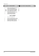
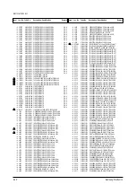
Страница 22: ...V KS6A 1 1 12 6003 001019 SCREW TAPTITE RH B M4 L12 ZPC BLK SWR 5 P F C S N A 1 13 AA96 01393A ASSY SPEAKER P 8ohm BT17MO 2W 350mm 1 S N A 1 14 6003 001023 SCREW TAPTITE RWH B M3 L10 ZPC YEL SW 2 SPK C S N A 1 15 AA63 00653A EARTH PLATE 150TP PBS 1 T0 3 3 C F 1 16 6003 001019 SCREW TAPTITE RH B M4 L12 ZPC BLK SWR 6 EARTH S N A 2 AA91 06043A ASSY CPT SMO 150TPV 1 S N A 2 1 AA60 10050R SCREW ASSY SW...

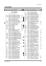
Страница 23: ...AA41 00829A PCB CONTROL SM5 210TP CEM 1 1L A 1 6T 24 1 1 12 6003 001019 SCREW TAPTITE RH B M4 L12 ZPC BLK SWR 5 P F C S N A 1 13 3001 001186 SPEAKER 3W 8OHM 80 æ2DB 270HZ 1 1 14 6003 001023 SCREW TAPTITE RWH B M3 L10 ZPC YEL SW 4 SPK C S N A 2 AA91 06042A ASSY CPT SMO 210TPV 1 S N A 2 1 3704 001105 SOCKET CRT 11P 20PI 26 5PI NI 1 V999S 2 2 AA96 01311A ASSY MISC P BRACKET CRT 210TP SECC T1 0 1 2 3 ...

Страница 24: ...0829A PCB CONTROL SM5 210TP CEM 1 1L A 1 6T 24 2 AA94 12556A ASSY PCB MAIN SMO 150TPV KS6A S N A 3 C801 2401 001426 C AL 470uF 20 400V GP 35x45mm 10 3 C818 2401 003633 C AL 220UF 20 160V GP ST 22X25MM 10 3 CN401 AA60 40012D PIN GT ASSY T1 6 6 12 5 NYLON66 S N A 3 CN501A AA39 20604A LEAD CONNECTOR ASSY 5 4P 300 200MM YBNH 3 CNT01 3710 001208 CONNECTOR SOCKET 32P 2R 2 54mm STRAIGHT 3 CNT01 AA96 0139...

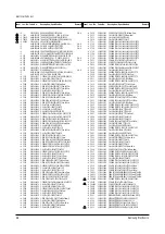
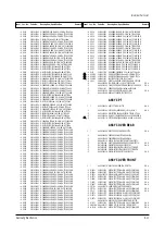
Страница 25: ... C705 2202 000121 C CERAMIC MLC AXIAL 100pF 10 50V Y5P TP 4 C706 2202 000121 C CERAMIC MLC AXIAL 100pF 10 50V Y5P TP 4 C707 2202 000121 C CERAMIC MLC AXIAL 100pF 10 50V Y5P TP 4 C708 2202 000121 C CERAMIC MLC AXIAL 100pF 10 50V Y5P TP 4 C802 2301 001065 C FILM MPPF 47nF 5 630V TP 19x15 5x7 7 4 C803 2301 001342 C FILM PPF 1 5nF 5 800V TP 15x6 5x11 5m 4 C804 2201 000281 C CERAMIC DISC 1NF 80 20 50V ...

Страница 26: ...YELET ID2 2 OD2 7 L3 1 SN BSS3 E EH S N A 4 EL07 6042 000001 EYELET ID2 2 OD2 7 L3 1 SN BSS3 E EH S N A 4 EL08 6042 000001 EYELET ID2 2 OD2 7 L3 1 SN BSS3 E EH S N A 4 EL09 6042 000001 EYELET ID2 2 OD2 7 L3 1 SN BSS3 E EH S N A 4 EL10 6042 000001 EYELET ID2 2 OD2 7 L3 1 SN BSS3 E EH S N A 4 EL11 6042 000001 EYELET ID2 2 OD2 7 L3 1 SN BSS3 E EH S N A 4 EL12 6042 000001 EYELET ID2 2 OD2 7 L3 1 SN BS...

Страница 27: ...0501 000283 TR SMALL SIGNAL KSA539 PNP 400mW TO 92 T 4 Q402 0502 001007 TR POWER KSC2073 H2 NPN 25W TO 220 ST 6 4 Q601 0501 000389 TR SMALL SIGNAL KSC815 NPN 400mW TO 92 T 4 Q603 0501 000389 TR SMALL SIGNAL KSC815 NPN 400mW TO 92 T 4 Q604 0501 000389 TR SMALL SIGNAL KSC815 NPN 400mW TO 92 T 4 Q605 0501 000389 TR SMALL SIGNAL KSC815 NPN 400mW TO 92 T 4 Q802 0501 000389 TR SMALL SIGNAL KSC815 NPN 40...

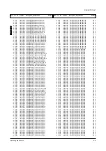
Страница 28: ... 000290 R CARBON 10KOHM 5 1 8W AA TP 1 8X3 2MM 4 R932 2001 000281 R CARBON 100OHM 5 1 8W AA TP 1 8X3 2MM 4 R933 2001 000281 R CARBON 100OHM 5 1 8W AA TP 1 8X3 2MM 4 R934 2001 000281 R CARBON 100OHM 5 1 8W AA TP 1 8X3 2MM 4 R935 2001 000281 R CARBON 100OHM 5 1 8W AA TP 1 8X3 2MM 4 R936 2001 000290 R CARBON 10KOHM 5 1 8W AA TP 1 8X3 2MM 4 R937 2001 000281 R CARBON 100OHM 5 1 8W AA TP 1 8X3 2MM 4 R93...

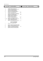
Страница 29: ...RY 210TP ABS HB IV16 SVM3 3 AA64 03286A KNOB POWER 210TP ABS HB IV16 3 AA64 03285A KNOB CONTROL 210TP ABS HB IV16 3 AA64 03284A PANEL CONTROL 150TP ABS HB IV16 ASSY ACCESSORY 1 AA92 07491A ASSY ACCESSORY SMO 210TPV 2 AA39 00344A CABLE FORM CONN COAX SMO 210TP UL2990 26 2 AA39 00343A CABLE FORM CONN COAX KS6A SMO 210TP UL29 2 BH39 10007A CBF POWER CORD DET 250V 6A H05VV F LP 34 2 AA69 00862A BAG PE...

Страница 30: ...0 400V GP 35x45mm 10 3 C818 2401 003633 C AL 220UF 20 160V GP ST 22X25MM 10 3 CN401 AA60 40012D PIN GT ASSY T1 6 6 12 5 NYLON66 S N A 3 CN501A AA39 20604A LEAD CONNECTOR ASSY 5 4P 300 200MM YBNH 3 CNT01 3710 001208 CONNECTOR SOCKET 32P 2R 2 54mm STRAIGHT 3 CNT01 AA96 01395A ASSY PCB P SMO 210TP 150TP KS6A TTSEC 8C S N A 3 CNT02 3710 001208 CONNECTOR SOCKET 32P 2R 2 54mm STRAIGHT 3 CR402S 2306 0003...

Страница 31: ...mm 4 C610 2401 000444 C AL 10uF 20 25V GP TP 5x5mm 5mm 4 C611 2401 000620 C AL 2 2uF 10 50V GP TP 5x11 5 4 C612 2401 002619 C AL 47uF 20 25V GP TP 5x11 5 4 C701 2202 000121 C CERAMIC MLC AXIAL 100pF 10 50V Y5P TP 4 C702 2202 000121 C CERAMIC MLC AXIAL 100pF 10 50V Y5P TP 4 C703 2202 000121 C CERAMIC MLC AXIAL 100pF 10 50V Y5P TP 4 C704 2202 000121 C CERAMIC MLC AXIAL 100pF 10 50V Y5P TP 4 C705 220...

Страница 32: ...J5 6B 5 6V 5 45 5 73V 500 4 DZ927 0403 000508 DIODE ZENER MTZJ5 6B 5 6V 5 45 5 73V 500 4 DZ928 0403 000508 DIODE ZENER MTZJ5 6B 5 6V 5 45 5 73V 500 4 EL01 6042 000001 EYELET ID2 2 OD2 7 L3 1 SN BSS3 E EH S N A 4 EL02 6042 000001 EYELET ID2 2 OD2 7 L3 1 SN BSS3 E EH S N A 4 EL03 6042 000001 EYELET ID2 2 OD2 7 L3 1 SN BSS3 E EH S N A 4 EL04 6042 000001 EYELET ID2 2 OD2 7 L3 1 SN BSS3 E EH S N A 4 EL...

Страница 33: ...TE BEAD AA 3 5x1 0x6 0mm 1500 4 L812 3301 000287 CORE FERRITE BEAD AA 3 5x1 0x6 0mm 1500 4 L815 2901 000297 FILTER EMI ON BOARD 3A 3 5x5 TP 4 L816 3301 000287 CORE FERRITE BEAD AA 3 5x1 0x6 0mm 1500 4 L901 2701 000114 INDUCTOR AXIAL 10uH 10 2 5x3 4mm 4 L902 2701 000158 INDUCTOR AXIAL 22uH 10 2 5x3 4mm 4 L903 2701 000158 INDUCTOR AXIAL 22uH 10 2 5x3 4mm 4 L904 2701 000158 INDUCTOR AXIAL 22uH 10 2 5...

Страница 34: ...8W AA TP 1 8X3 2MM 4 R924 2001 000281 R CARBON 100OHM 5 1 8W AA TP 1 8X3 2MM 4 R925 2001 000281 R CARBON 100OHM 5 1 8W AA TP 1 8X3 2MM 4 R926 2001 000429 R CARBON 1KOHM 5 1 8W AA TP 1 8X3 2MM 4 R927 2001 000281 R CARBON 100OHM 5 1 8W AA TP 1 8X3 2MM 4 R928 2001 000290 R CARBON 10KOHM 5 1 8W AA TP 1 8X3 2MM 4 R929 2001 000281 R CARBON 100OHM 5 1 8W AA TP 1 8X3 2MM 4 R930 2001 000281 R CARBON 100OHM...

Страница 35: ...1 00048A EARTH PLATE PG21LS PBS T0 2 S N A 3 BH71 10402A EARTH PLATE CSH780B PBS 1 T0 3 S17I S N A 2 AA96 01307A ASSY COVER P FRONT SMO 210TPV 3 SPK C 6003 001023 SCREW TAPTITE RWH B M3 L10 ZPC YEL SW S N A 3 3001 001186 SPEAKER 3W 8OHM 80 æ2DB 270HZ 3 AA64 03279A CABINET FRONT 210TP ABS HB IV16 3 AA65 00011C CLAMPER CORE WIRE ALL MODEL NYLON 66 V2 S N A ASSY ACCESSORY 1 AA92 07491A ASSY ACCESSORY...

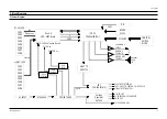
Страница 36: ... 3W 200V TO CRT VIDEO B 16 5V 16 5V TO VERT AMP H D T DRIVE 6 3Vac TO CRT HEATER 3 3V TO VOC 5V TO EEPROM EXPANDER IC 8V TO VOC 13V TO SOUND AMP RGB AMP TDA6107Q SOUND AMP TDA7267 Y C R T C VOICE VOICE Video In Mux b d SOM 080P Board H OUT TR KSD5703 E2 PROM 24C04 PCF8574P MIC CONTROL SWITCH BLCOK IC MCU TDA9381PS N2 I CAM1 CAM2 CAM3 CAM4 CAM5 CAM6 CAM7 CAM8 or BNC JACK CAM1 CAM2 CAM3 CAM4 CAM5 CA...

Страница 37: ...8 PCB Diagrams Samsung Electronics PCB Diagrams 8 1 8 1 PATTERN ...

Страница 38: ...8 2 TOP PCB Diagrams 8 2 Samsung Electronics ...

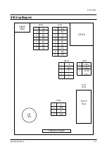
Страница 39: ...CORD CRT PCB Mux b d Block 1 2 3 4 5 6 7 1 2 3 4 5 6 7 8 9 GND OT4 OT5 OT6 OT7 OT9 IN9 IN10 IN11 5V LED RT1 RT2 RMC GND MIC CN902 CN901 1 2 3 4 5 IK GND B G R CN501A 1 2 3 GND GND SOUND OUT CN601 CNT01 CNT02 1 2 3 4 HT GND N C 200V CN402 FBT T444 VIDEO JACK BLOCK ...

Страница 40: ...9 2 Samsung Electronics MEMO ...

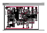
Страница 41: ...10 Schematic Diagrams Samsung Electronics Schematic Diagrams 9 1 10 1 MAIN 1 ...

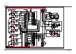
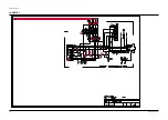
Страница 42: ...10 2 MAIN 2 Schematic Diagrams 9 2 Samsung Electronics ...

Страница 43: ...10 3 MAIN3 Samsung Electronics Schematic Diagrams 9 3 ...

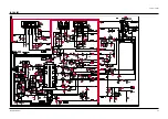
Страница 44: ...10 4 MAIN 4 Schematic Diagrams 9 4 Samsung Electronics ...

Страница 45: ...ELECTRONICS Samsung Electronics Co Ltd Dec 2002 Printed in Korea AA82 00253A ...

Отзывы: