5-2
Flow chart of Troubleshooting and Circuit Diagram
5-2 Initial
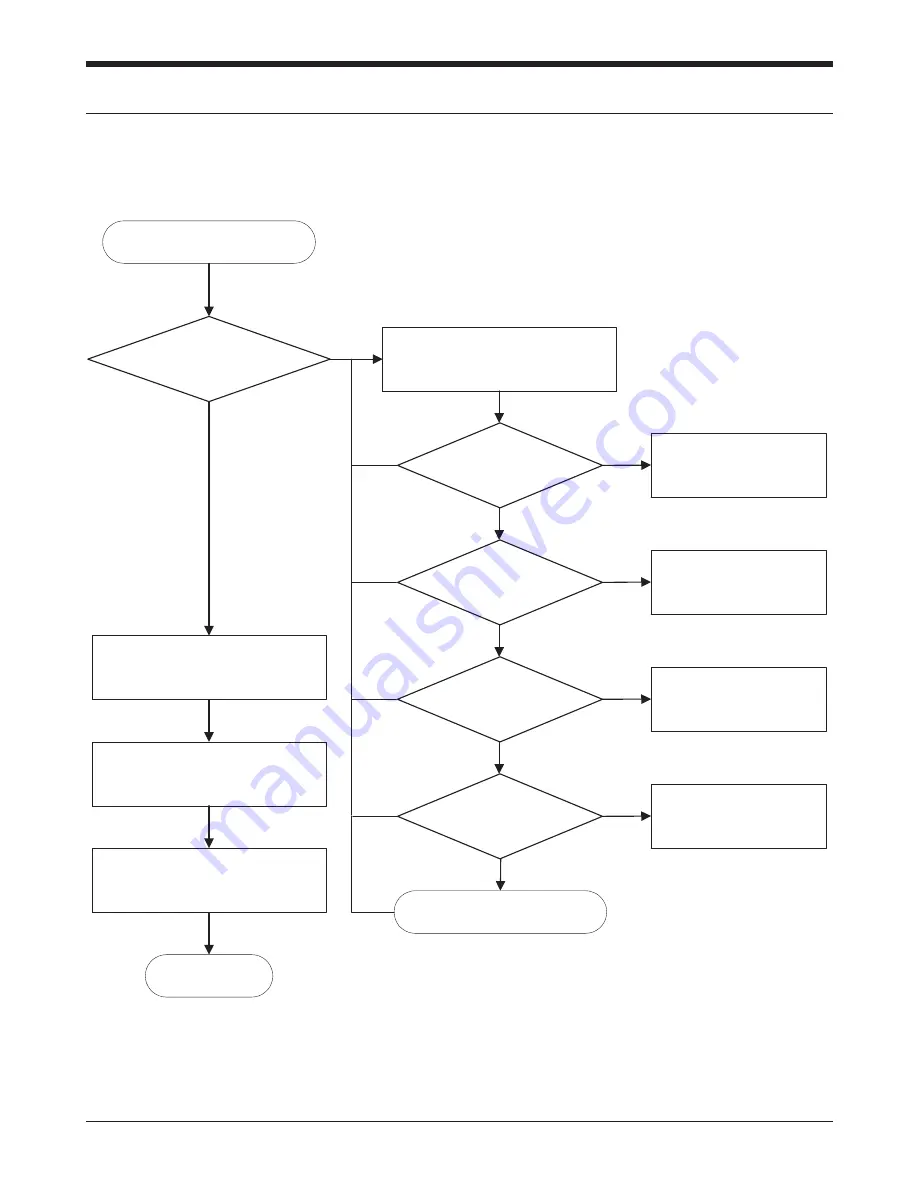
Initial Failure
Check and repair the important
signals of U400 as follows
END
No
U302 pin 6 = "H" ?
The node
between R401 and C404
= "H" (RST)
No
Check U103
R409 = "H"
(SIMPWDN_BOOT)
No
Resolder R409
Yes
R428 = "H"
(GPIO4_MSIZE)
No
Resolder R428
Yes
R429 = "L"
(GPIO2_EXTPROC)
No
Resolder R429
Yes
Replace PBA
Check all the other connection
by Test S/W
Check the circuit around LCD
Check the circuit
around U401(EEPROM)
and data stored in it
Yes
Содержание SGH-T100
Страница 2: ...Samsung Electronics Co Ltd Printed in Korea 04 2002 Rev 1 0 GH68 02699A ELECTRONICS ...
Страница 12: ...1 10 Exploded Views and Parts List 1 10 Battery Charger BATTERY CHARGER GH44 00279A ...
Страница 13: ...2 PCB Diagrams 2 1 Main Top PCB Diagrams 2 1 ...
Страница 14: ...2 2 Main Bottom PCB Diagrams 2 2 ...
Страница 40: ...5 14 Flow chart of Troubleshooting and Circuit Diagram U400 CN201 REC PWO1P PW01N 7 17 REC REC ...


