background image

English_31


C

A

me
RA
 Ope

RATION

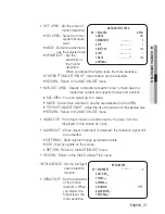
DET. AREA :  Set the areas of 

motion detection.

SEL AREA :  Select from four 

areas that users 

want.

MODE :  Determine whether to 

use the selected area.

SENSITIVITY :  Set the 

sensitivity of 

the motion 

detection. 

When you adjust the higher level, the more sensitive.

TOP/BOTTOM/LEFT/RIGHT :  Area location can be adjusted.

RETURN :  Return to the MOTION DET menu.

NON DET. AREA :  Specify a detection exception area to mask.Select a 

mask area number and specify the size and position.

  SEL AREA : You can select up to 4 areas.

  MODE :  Determines whether to use the area selected in the AREA.

  TOP/BOTTOM/LEFT/RIGHT :  Adjust the size and position of the selected area.

RETURN :  Return to the MOTION DET menu.

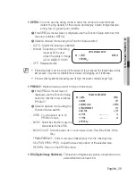
INDICATOR :  If an object moves in a pattern set by the user, it will be 

displayed on the screen as a box.

ALARM OUT :  When object movement is detected, the detection signal will 

be outputted.

EXTERNAL : Send signals through external terminals.

OSD : Display signals on the screen.

RETURN : Return to the MOTION DET menu.

RETURN :  Return to the VIDEO ANALYTICS menu.

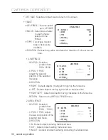
INTELLIGENCE :  Set the intelligent 

video detection 

function.

SENSITIVITY :  Set the sensitivity 

of the motion 

detection. When 

you adjust the 

higher level, the 

more sensitive.


-

MOTION DETECT AREA

 1. 

SEL AREA


AREA

1

  2. 

MODE


ON

  3. 

SENSITIVITY


----

---- 

5

  4. 

TOP


-------- 

1

  5. 

BOTTOM


--------


100

  6. 

LEFT


-------- 

1

  7. 

RIGHT


--------


100

  8. 

RETURN

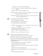
INTELLIGENCE

 1. 

SENSITIVITY


----

---- 

5

  2. 

DET. SIZE


  3. FENCE   
  4. APPEAR 
  5. INDICATOR  


OFF

  6. 

ALARM OUT


  7. 

RETURN


Содержание SCV-5083

Страница 1: ...High Resolution WDR Vandal Resistant Dome Camera User Manual SCV 5083 ...

Страница 2: ...aimer Samsung Techwin makes the best to verify the integrity and correctness of the contents in this document but no formal guarantee shall be provided Use of this document and the subsequent results shall be entirely on the user s own responsibility Samsung Techwin reserves the right to change the contents of this document without prior notice Warranty If the product does not operate properly in ...

Страница 3: ...and correct input power voltage To help you understand this manual thoroughly we ll introduce our model description SCV 5083 SERIES NTSC MODEL PAL MODEL SCV 5083N SCV 5083P MODEL DESCRIPTION SCV 5083X _ SIGNAL SYSTEM N NTSC MODEL P PAL MODEL SIGNAL SYSTEM ...

Страница 4: ...zard do not expose this appliance to rain or moisture To prevent injury this apparatus must be securely attached to the floor wall in accordance with the installation instructions WARNING Be sure to use only the standard adapter that is specified in the specification sheet Using any other adapter could cause fire electrical shock or damage to the product Incorrectly connecting the power supply or ...

Страница 5: ... objects on the product or apply strong shock to it Keep away from a location subject to excessive vibrationor magnetic interference Do not install in a location subject to high temperature over 55 C low temperature below 10 C or high humidity Doing so may cause fire or electric shock If you want to relocate the already installed product be sure to turn off the power and then move or reinstall it ...

Страница 6: ... be disposed of with other household waste at the end of their working life Where marked the chemical symbols Hg Cd or Pb indicate that the battery contains mercury cadmium or lead above the reference levels in EC Directive 2006 66 If batteries are not properly disposed of these substances can cause harm to human health or the environment To protect natural resources and to promote material reuse ...

Страница 7: ...apparatus Only use attachments accessories specified by the manufacturer Use only with cart stand tripod bracket or table specified by the manufacturer or sold with the apparatus Unplug this apparatus when a card is used Use caution when moving the cart apparatus combination to avoid injury from tip over Refer all servicing to qualified service personnel Servicing is required when the apparatus ha...

Страница 8: ...12 Before installation 12 Installation 15 Adjusting the monitoring direction for the camera connection 16 16 Connecting to Monitor 16 Connecting to Power 17 Using Coaxial Communications camera operation 19 19 Menu Configuration 19 Menu Setup troubleshooting 35 35 Troubleshooting specifications 36 36 Specifications 38 Dimension ...

Страница 9: ...e dark place Day Night This camera has a function that automatically selects the mode that is appropriate for daytime or night time conditions The COLOR mode operates in daytime condi tions to provide optimum colors and B W mode operates in night time conditions to enhance the definition of the image SSDR Samsung Super Dynamic Range If an object has a large variance between bright and dark areas i...

Страница 10: ...munications Pelco Coaxitron OSD The camera s OSD is complimented by 17 languages English Chinese Korean Japanese German Italian French Spanish Russian Czech Polish Romanian Serbian Swedish Danish Turkish Portuguese Components and Accessories Check if the following items are included in the product package Quick Manual SCV 5083 o Gy G kyG Ty Gk Gj SCV 5083 Quick Manual Screws Video Output Cable Tem...

Страница 11: ...or after changing a selected item 6 Video Output Terminal to Monitor 7 Pan Base Control panning angle of camera 8 Power Input Connector 9 Ground Terminal D N Input Terminal You can switch to Day Night Mode by connecting an external signal to this terminal MD Output Terminal Motion detection signals are output through this terminal Video Output Jack Video signals are output through this port Connec...

Страница 12: ...ght in improper place or the electric line cover to be damaged Otherwise it may cause a breakdown or fire Before installing your camera you have to adjust the lens focus zoom and switch settings When installing your camera don t allow any person to approach the installation site INSTALLATION Disassembling Using the L wrench provided loosen 3 screws by turning them counterclockwise and separate the...

Страница 13: ...ot included fully into the holes Fix the case bed on the ceiling by using Tapping screws TH M4 x L30 3 places Tapping screw Connect Power and video cables and arrange them through the hole you want to pass when mounting the main body on the mounting bracket note that not to damage or squeeze the cables Power input terminal Function jack Video output jack TOP FRONT 1 2 ...

Страница 14: ...n its mounting bracket with the three screws using L Wrench The installation should be done by qualifi ed service personnel or system installers If the ceiling material is not strong enough to hold the installation screws the camera may fall off Reinforce the ceiling as needed 3 4 5 M Shield case Dome cover TOP FRONT ...

Страница 15: ...ng the lens on its axis is called Rotation The effective range of pan is a total of 354 degrees The effective range of rotation is a total of 355 degrees The effective range of tilt is a total of 68 degrees Methods of adjustment After installing the camera adjust the panning angle in consideration of the monitoring direction Set the horizontal angle so that the image is not reversed Adjust the til...

Страница 16: ... of the camera to a monitor As the connecting method varies with the instruments refer to the manual supplied with the instrument Only connect the cable when the power is turned off Connecting to Power You can connect power as shown in the following figure SCV 5083 Monitor Power Input Terminal ...

Страница 17: ...rd voltage for camera operation DC 12V 10 AC 24V 10 There may be some deviation in voltage drop depending on the type of wire and the manufacturer Be sure to connect power only after all the installation is complete Using Coaxial Communications Coaxial Communications System OSD Control method CAMERA DVR CONTROLLER SET MENU ENTER OSD KEY UP UP KEY JOYSTICK UP DOWN DOWN KEY JOYSTICK DOWN LEFT LEFT K...

Страница 18: ... cause issues with the communication over the coaxial cable To ensure picture quality only single channel video output connector can be used while camera connected to other video equipments M Video Cable The camera s video output port is connected to the monitor with a BNC coaxial cable shown below If the distance between the camera and the monitor exceeds the recommended maximum please use an aux...

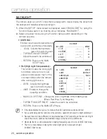
Страница 19: ...UAL AWC SET MERCURY EXPOSURE BRIGHTNESS LENS SHUTTER AGC SSNR4 RETURN BACKLIGHT OFF USER BLC HLC WDR SPECIAL DISPLAY COMM ADJ IMAGE ADJ DAY NIGHT DEFOG PRIVACY DIS VIDEO ANALYTICS RETURN EXIT SAVE NOT SAVE RESET Menu Setup For function setting you can use the function setting switch inside the dome cover camera operation VIDEO SET Function Setup switch ...

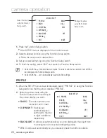
Страница 20: ... Setup switch so that the arrow indicates PROFILE Select a desired mode using the Function Setup switch according to the picture display you want BASIC The most common envi ronment is set to meet DAY NIGHT It will be set automatically so it optimizes to the day or night conditions respectively BACKLIGHT It will be set automatically so you can distinguish the object from the background in a severe ...

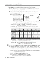
Страница 21: ...H WHITE BAL ATW ATW ATW OUTDOOR INDOOR BACKLIGHT OFF OFF USER BLC OFF OFF SSNR4 ON ON ON ON ON DAY NIGHT AUTO AUTO AUTO AUTO AUTO If you select the traffic monitoring mode the shutter will be set to 1 200 sec Noise can be detected at night M SSDR Samsung Super Dynamic Range If an object has a large variance between bright and dark areas it will keep bright areas bright and make selected dark areas...

Страница 22: ...lly Set White Balance first by using the ATW or AWC mode After that button to MANUAL mode fine tune the White Balance and the Function Setup switch AWC SET To find the optimal luminance level for the current environment point the camera towards a sheet of white paper and press the Function Setup switch If the environment changes readjust it Mercury This is an auto compensation function that optimi...

Страница 23: ...ture flicker this happen when there is a clash with the installed lighting frequency The greater the shutter value the brighter the screen is but the more the residual images of objects there are If the min shutter value is large it can cause noise spots and white areas but still operate normally If you do not use the AGC mode on the exposure menu it cannot be set above 1 60sec Depending on the se...

Страница 24: ...sts the brightness level of a monitoring area LIMIT Enable to change the operating condition MASK COLOR TONE Change the color brightness of the masking area Black Red Blue Cyan Magenta TOP BOTTOM LEFT RIGHT Adjust the area to be enhanced RETURN Return to the MAIN SETUP menu If the white balance menu is set to manual then HLC performance can be limited If you use the defog and HLC functions at the ...

Страница 25: ...h to adjust the brightness of the WDR setup WDR ON WDR OFF RETURN Return to the MAIN SETUP menu In WDR mode the max min shutter value is set to 1 2 to 1 240 In WDR mode there can be noise between a bright and dark area Depending on light conditions unnatural changes or symptoms can occur on the screen so deactivate the user mode M WDRSETUP 1 LEVEL MIDDLE 2 RETURN ...

Страница 26: ...tup switch The entered title appears on the screen Select the position to display the title on the screen by using the Function Setup switch and press the Function Setup switch When the position is determined select END and press the Function Setup switch to return to the DISPLAY menu When the CAM TITLE menu is OFF no title will be displayed on the monitor screen even if you enter one and Numbers ...

Страница 27: ...e smaller the setting value is the smaller the color gain gets and the more color blind it gets H REV Flip an image horizontally V REV Flip an image vertically D ZOOM You can use a digital zoom of x1 x16 SHARPNESS Select a mode to adjust the thickness of an image s sharpness Increase or decrease the level of each mode to adjust the level of sharpness Depending on the image adjust it to an appropri...

Страница 28: ...3 2 4 9 0 5 8 SLOW 4 1 12 5 2 5 8 5 0 9 7 5 NORMAL 4 2 12 2 6 8 1 3 7 FAST 4 3 11 5 2 7 7 5 1 7 6 8 VERY FAST 4 4 11 2 8 7 2 1 6 6 Depending on the installation environment and the exposure menu s gain mode setting the switching brightness may vary DWELL TIME You can select day night switching delay time from 3s 5s 7s 10s 15s 20s 30s 40s 60s If you set the AGC mode to off on the exposure menu you ...

Страница 29: ...le fog and the manual fog level is high the screen contrast can get high PRIVACY Mask an area you want to hide on the screen If the SPECIAL menu screen is displayed use the Function Setup switch so that the arrow indicates PRIVACY Select a desired mode using the Function Setup switch AREA You can select up to 24 PRIVACY areas MODE Determines whether to use the area selected in the AREA MASK COLOR ...

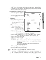
Страница 30: ... malfunction In a monitoring environment with a simple background or an environment with low light level or at night the detection performance can deteriorate Sudden changes in the lighting and severe camera shaking can be wrongly detected as tampering Immediately after tampering the camera tampering detection can take up to a max of five seconds If camera tampering is detected after some time fiv...

Страница 31: ... Adjust the size and position of the selected area RETURN Return to the MOTION DET menu INDICATOR If an object moves in a pattern set by the user it will be displayed on the screen as a box ALARM OUT When object movement is detected the detection signal will be outputted EXTERNAL Send signals through external terminals OSD Display signals on the screen RETURN Return to the MOTION DET menu RETURN R...

Страница 32: ...to right on the fence line LEFT Detects objects moving right to left on the fence line RIGHT LEFT Detects all objects moving crosswise on the fence line RETURN Return to the VIRTUAL FENCE menu 2 AREA FENCE SEL POS Selects a position from POS1 POS4 X POS Y POS Adjust the size and position of the selected area fence DIRECTION IN Detects objects entering the fenced area OUT Detects objects exiting th...

Страница 33: ...lay signals on the screen RETURN Return to the INTELLIGENCE menu RETURN Return to the VIDEO ANALYTICS menu Before use set the max min movement size within the range Depending on the shape of an object there can be errors in size detection From the top of the screen a max of sixteen objects can be expressed If the camera shoots an object a short distance away the video analysis function can be degr...

Страница 34: ... the max size or smaller than the min size motion is not detected To avoid false detection caused by noises set the max min detection size suitable for the installation environment But the same movement in the same location can cause a different detection size So include margins when you set the min max detection size EXIT Select a desired EXIT mode using the Function Setup switch depending on the...

Страница 35: ...hange the camera position The image on the screen is dark Adjust the contrast feature of the monitor or DVR If you have an intermediate device set the 75Ω Hi z properly The camera is not working properly and the surface of the camera is hot Check that you have properly connected the camera to an appropriate power source he DAY NIGHT menu does not work Check that AGC of EXPOSURE SETUP menu is OFF T...

Страница 36: ...E 0 00003Lux 1sec F1 2 30IRE S N Ratio 52dB AGC off Weight on Video Output CVBS 1 0 Vp p 75Ω composite Lens Type Focal Length Zoom Ratio 2 8 10 5mm Max Aperture Ratio F1 2 Angular Field of View H 91 5 Wide 27 7 Tele V 68 3 Wide 20 8 Tele Min Object Distance 0 5m Focus Control Manual Lens Type DC Auto Iris Mount Type Board Type Operational On Screen Display English Chinese Korean Japanese German It...

Страница 37: ...anual AWC MERCURY 1 800K 10 500K Electronic Shutter Speed 1 sec 1 12 000 sec Digital Zoom Off On 1x 16x Reverse Off H Rev V Rev HV Rev Profile Basic Day Night Backlight ITS Indoor User Alarm 1 Out Communication Coaxial Control SPC 300 Compatible Protocol Coax Pelco C Coaxitron Environmental Operating Temperature Humidity 10 C 55 C Less than 90 RH Ingress Protection IP66 Vandal Resistance IK10 Elec...

Страница 38: ...38_ specifications Dimension Unit mm ...

Страница 39: ...MEMO ...

Страница 40: ...147 8740 60 FAX 82 31 8018 3745 SAMSUNG TECHWIN EUROPE LTD Samsung House 1000 Hillswood Drive Hillswood Business Park Chertsey Surrey UNITED KINGDOM KT16 OPS TEL 44 1932 45 5300 FAX 44 1932 45 5325 SAMSUNG TECHWIN AMERICA Inc 100 Challenger Rd Suite 700 Ridgefield Park NJ 07660 Toll Free 1 877 213 1222 Direct 1 201 325 6920 Fax 1 201 373 0124 www samsungcctvusa com SALES NETWORK ...

Отзывы: