


14_
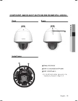
connection & installation
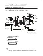
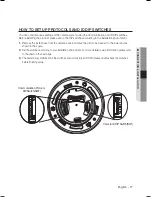
CAMERA WIRING INTERFACE BOARD
For the camera wiring, please refer to the picture below.
(When using coaxial communication, a separate control signal connection is not required.)
• RS485 Communications
• RS422 Communications
Camera
Camera
RX+
RX-
RX+
RX-
TX+
TX-
TXD+
TXD-
TXD+
TXD-
RXD+
RXD-
Controller
or DVR
Controller
or DVR
Control Signal Connection
The max voltage and capacity of the Alarm OUT/AUX OUT ports are 30VDC/2A and 24VAC/2.5A, respectively.
Connecting the power connector and GND incorrectly to the NC/NO and COM ports may cause a short circuit and fi re,
damaging the camera.
M
connection & installation
IN8
IN7
IN6
IN5
GND
RX
RX
3.COM 3.NO
FG
2.COM
2.NO
2.NC
IN4
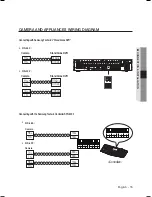
Communications and Alarm/AUX
Refer to the below Control
Signal Connection chart
Power Supply
AC24V 2.5A
Alarm/AUX
Alarm/
AUX Output 1
Alarm Input
1~4
Power Input
Alarm/
AUX
Output 3
Ground
Alarm
Input
5~8
Alarm/
AUX Output 2
Ú
After connecting the power cable by
separating the power connector from the
terminal, make the connection between
terminal and connector by using a bolt.
Содержание SCP-2373
Страница 1: ...SPEED DOME CAMERA User Manual SCP 2373 SCP 2373H SCP 2273 SCP 2273H ...
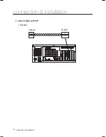
Страница 16: ...16_ connection installation connection installation ToconnecttoSamsungPCDVR RS 485 y Camera RX RX PC DVR ...
Страница 85: ...English 85 PRODUCT SPECIFICATIONS DIMENSIONS Indoor Model Ø152 5 98 Ø133 2 5 24 Unit mm Inches ...
Страница 87: ...MEMO ...