


SPEED DOME CAMERA
User Guide
12
SPEED DOME CAMERA
User Guide
13
1
3
2
5
4
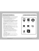
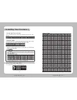
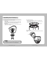
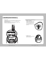
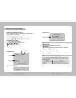
Components and Accessories
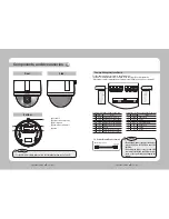
Side
Bottom
1
Screw Hole
2
Communication Setup Switch
3
ID Setup Switch
4
Video/Communication/Power
5
Alarm
Front
•FortheDIPswitchsettings,pleaserefertothe“InstallingYourCamera”onPage17.
Notes
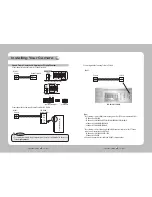
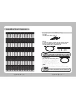
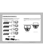
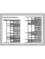
For the camera wiring, please refer to the picture below.
The camera's wiring interface board is fitted to the housing, this is sold separately.
(When using coaxial communication, a separate control signal connection is not required.)
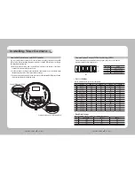
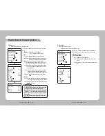
•Themaximumpowercapacityofthebuilt-in
relay is 30V DC/2A, 125V AC/0.5A, and 250V
AC/0.25A.
•ConnectingthepowerconnectorandGND
incorrectly to the NC/NO and COM ports may
cause a short circuit and fire, damaging the
camera.
Notes
Camera Wiring Interface Board
· RS485 Communications
Camera
485+
485-
R+/RX+
R-/RX-
Controller
or DVR
Control Signal Connection
Power, Video & Communication Signal Connection
Controller & Auxiliary Signal Connection
Alarm
Video Controller Power Supply
No.
Name
Usage
1
VIDEO
Video Output
2
GND
Ground
3
485+
Controller Data Line
4
485-
Controller Data Line
5
FG
Field Ground
6
AC
AC 24V
7
AC
AC 24V
No.
Name
Usage
1
2.COM
Alarm Output 2 (Common)
2
2.NO
Alarm Output 2 (Normal Open)
3
1.COM
Alarm Output 1 (Common)
4
1.NO
Alarm Output 1 (Normal Open)
5
1.NC
Alarm Output 1 (Normal Open)
6
GND
Ground
7
IN1
Alarm Input Sensor Terminal 1
8
IN2
Alarm Input Sensor Terminal 2


