background image

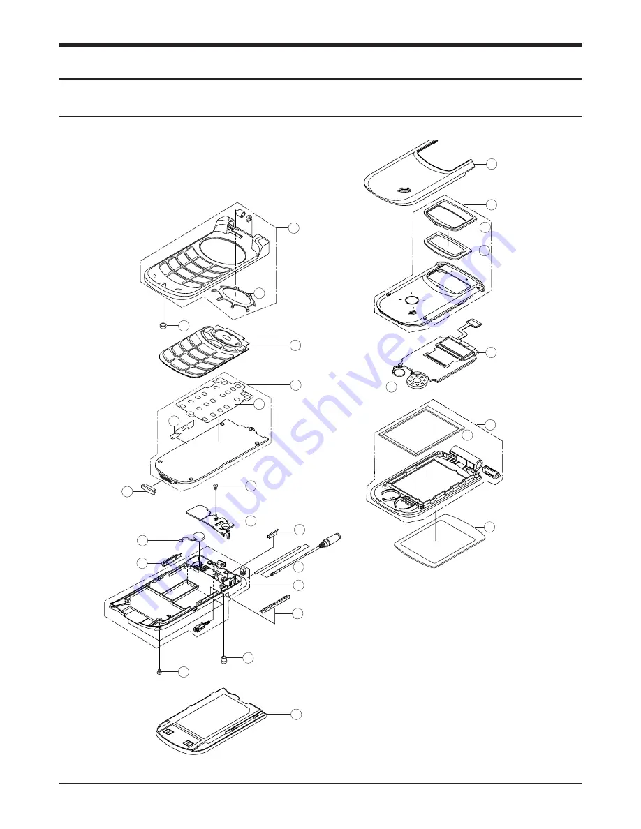
9.  Exploded View and Parts List

9-1 SCH-A310SS/XAR  Main

SAMSUNG Proprietary-Contents may change without notice

9-1

5

6

7

4

3

2-2

2

1

8

9

10

10-1

10-2

11

12

13

14

17

19

18

15

16

19

20

21

7-1

2-1

5-1

Содержание SCH-A310 Series

Страница 1: ...HONE CONTENTS 1 General Introduction 2 Specification 3 Installation 4 NAM Programming 5 Product Support Tools 6 Circuit Description 7 Test Procedure 8 Trouble Shooting 9 Exploded Views and Parts List 10 Block Diagram 11 Electrical Parts List 12 PCB Diagrams 13 Circuit Diagrams ...

Страница 2: ... Samsung Electronics Co Ltd August 2002 Pinted in Korea Code No GH68 03090A BASIC ELECTRONICS ...

Страница 3: ...Dual mode Wideband Spread Spectrum Cellular Systems TIA EIA IS 125 Recommended Minimum Performance standards for Digital Cellular Wideband Spread Spectrum Speech Service Option1 TIA EIA IS 126 A Mobile Station Loop back Service Option standard TIA EIA IS 95B Mobile Station Base Station Compatibility Standard for Dual Mode Wideband Spread Spectrum Cellular Systems for the analog air interface TIA E...

Страница 4: ...ission 1M25F9W 1M25F9W 40K0F8W 40K0F1D In Output Impdance 50Ω 50Ω 50Ω Tx Intermediate Frequency 263 6MHz 228 6MHz 228 6MHz Rx Intermediate Frequency 183 6MHz 183 6MHz 183 6MHz 1st FTX 263 6MHz 1st FTX 228 6MHz 1st FTX 228 6MHz Tx Local Frequency 2nd 527 2MHz 2nd 457 2MHz 2nd 457 2MHz 1st FRX 183 6MHz 1st FRX 183 6MHz 1st FRX 183 6MHz Rx Local Frequency 2nd 367 2MHz 2nd 367 2MHz 2nd 367 2MHz TCXO F...

Страница 5: ...MHz Channel Spacing 50kHz Number of Channels 1200 Duplex Seperation 80 MHz Type of Emission 1M25F9W Input Output Impedance 50 ohms Intermediate Freequency Transmitter 263 6MHz Receiver 183 6MHz Local Frequency Transmitter 1st FTX 263 6MHz 2nd 527 2MHz Receiver 1st FRX 183 6MHz 2nd 367 2MHz TCXO Frequency 19 2MHz Frequency Stability FRX 80MHz 150Hz Operation Temperature 30deg 60deg Supply Voltage 3...

Страница 6: ...3MHz Conducted Spurious Emission 1 25 MHz 42dBc 30kHz RECEIVER Rx Sensitivity and Dynamic Range 104dBm FER 0 5 or less 25dBm FER 0 5 or less Conducted Spurious Emission 1930 1990 MHz 81dBm 1850 1910 MHz 61dBm All Other Frequencies 47dBm Single Tone Desensitization lower than 1 Rx power level 101dBm Tone power level 30dBm Tone offset from carrier 1 25 MHz Intermodulation Spurious Response Attenuati...

Страница 7: ... Type of Emission 1M25F9W Input Output Impedance 50 ohms Intermediate Freequency Transmitter 228 6MHz Receiver 183 6MHz Local Frequency Transmitter 1st FTX 228 6MHz 2nd 457 2MHz Receiver 1st FRX 183 6MHz 2nd 367 2MHz TCXO Frequency 19 2MHz Frequency Stability FRX 45MHz 300Hz Operation Temperature 30deg 60deg Supply Voltage 3 8V TRANSMITTER Waveform Quality 0 944 or more Open Loop Power Control Ran...

Страница 8: ...m FER 0 5 or less Conducted Spurious Emission 869 894 MHz 81dBm 824 849 MHz 61dBm All Other Frequencies 47dBm Single Tone Desensitization lower than 1 Rx power level 101dBm Tone power level 30dBm Tone offset from carrier 900KHz Intermodulation Spurious Response Attenuation lower than 1 Tone 1 offset from carrier 900KHz Tone 2 offset from carrier 1 700MHz Test 1 2 Rx power 101dBm Tone 1 power 43dBm...

Страница 9: ... 140 F Modulation Demodulation Voice FM Data PM Operating Temperature 30deg 60deg 22 F 140 F Supply Voltate 3 8V TRANSMITTER RF output power 27dBm Carrier ON OFF conditions ON Condition within 3dB of specification output in 2 ms OFF Condition below 60dBm in 2ms Compresssor Compression Rate 2 1 Attack Time 3ms Recovery Time 13 5ms Reference Input input power level for producing a nominal 2 9kHz pea...

Страница 10: ... dB For modulation by WBD without SAT and ST with SAT fo 45 kHz fo 60 kHz above 45 dB fo 60 kHz fo 90 kHz above 65 dB fo 90 kHz 2 fo above 63 dB 10 LOG PY dB where fo carrier frequency PY mean output power in watts Harmonic and conducted Spurious Emissions below 43 10 LOG PY dB RECEIVER De emphasis 6dB OCT within 0 3 3 kHz Expandor Expandor Rate 1 2 Attack time within 3 ms Recovery Time within 13 ...

Страница 11: ... below 60 dBm Receive Band below 80 dBm Out of Band Conducted Spurious Emissions below 47dBm Radiated Spurious Emission Frequency Range Maximum Allowable EIRP 25 70MHz 45dBm 70 130MHz 41dBm 130 174 MHz 41 32dBm 174 260 MHz 32 dBm 260 470 MHz 32 26 dBm 470 1G MHz 21 dBm 2 5 1500MHz GPS GENERAL Frequency Range 1574 1576 MHz ...

Страница 12: ...Initialization 5 Waiting for order 6 Waiting for answer 7 Conversation state 8 Exit 4 T xx Tx adjust Value ranges from 63 63dB 5 Dxxx Sector power in dBm 6 xx ec lo 7 Pxxx PN offset 8 CHxxxx Channel number 9 TV Tx vocoder rate 8 is full rate 1 is 1 8th rate 10 RV Rx vocoder rate 8 is full rate 1 is 1 8th rate 11 xx Walsh code used in traffic channel 12 System acquisition state 2 6 PCS Debug Displa...

Страница 13: ...ng Frequency Band A Band or B Band 5 RSSIxxx RSSI value 6 CHxxx Channel number 7 Handset Status 1 Initialization state 2 Idle state 3 System Access state 4 Voice channel state 8 System acquisition state 2 7 AMPS Debug Display Information To select debug display mode Press MENU 0 0 and press 0 4 0 7 9 3 and press 1 SIDxxxxx x x PWRx RSSIxxx SATx CHxxxx xx xx 1 2 3 5 6 8 7 4 ...

Страница 14: ... it into the adaptor outlet at the bottom of the phone 2 Connect the adaptor to a standard 110 220 free volt AC wall outlet The battery will begin charging immediately and the LED located at the top of your phone will light and remain red while the battery icon animates the icon will remain animated even if the phone is turned off during charging 3 The LED indicates the status of the battery being...

Страница 15: ...he two large slotted screws See the figure 3 2 3 Drill holes and mount the lower half of the clamshell by using the screws 4 Place the cradle onto the remaining half of the clamshell and assemble them by using the screws 5 Reassemble the two halves of the clamshell together Adjust the mounting angle and tighten the two slotted screws Figure 3 2 Cradle Installation CLAM SHELL MOUNT UPPER CLAM SHELL...

Страница 16: ...nto the appropriate position 3 3 4 Hands Free Microphone 1 It is recommended to install the microphone where it is 30 45 cm 12 18 away from the driver Choose the location where is least susceptible to interference caused by external noise sources ie adjacent windows car audio speakers etc Normal place is the sun visor 2 Once the microphone has been correctly positioned connect the microphone wire ...

Страница 17: ...nnect the other end of the power cable to the PWR jack of the hands free box Notes It is recommended to connect the power cable directly to the battery to avoid power noise Make sure the connection between the battery terminal and vehicle chassis is made correctly Make sure the fuse having a proper capacity is used on the power cable Make sure the cables do not pass over any sharp metal edge that ...

Страница 18: ...D pairs or selecting between Yes No use the Up Down navigation key A For changing Home SID NID pairs select from SID NID pair numbers 01 to 20 by pressing Up navigation key Press edit by pressing Menu key to change setting Press OK key to save setting B For changing Forn SID or NID Registration Home Sys Registration etc press Up Down navigation key to select between Yes or No Press OK key to save ...

Страница 19: ...ble as follows 1 Press 4 7 6 8 1 3 5 8 0 in idle mode 001 031 MRU2 TABLE then MRU00 yzxxxx where y is Mode definition 1 Analog 2 Digital z is Band Class 0 800MHz 1 1 9GHz and xxxx is Channel number or A or B band for AMPS MRU00 to MRU11 total of 12 MRU entries available Ex for CDMA 800MHz Channel 384 in 4th MRU entry order MRU03 200384 will display Ex for PCS 1 9GHz Channel 150 in 7th MRU entry or...

Страница 20: ...cting Markov New 13k 4 The MS will originate the Markov call using the first entry in the outgoing call list 5 If the outgoing call list is empty no outgoing call made the MS will originate to a default number of 1234567 4 8 Fax Data Calls 1 Press Menu 8 7 in idle mode 2 Toggle among Data Fax Off Fax for Next Call Fax until Powered Off Modem for Next Call Modem until Powered Off using Navigation U...

Страница 21: ...message at 2 Message then press OK key to store Press Menu key to select from ABC Number T 9 Word or Symbol mode 6 Enter Call back number at 3 Call Back then press OK key to store 7 At 4 Options scroll using Up Down navigation key and select from options using Left Right navigation key for the Priority level Validity Period Send Later option Delivery Ack On or Off or Save Message option 8 At 5 Act...

Страница 22: ...t for port number setting change Select from Port 1 2 or 3 for IP Address 1 2 or 3 then select from Port A Port B or Port C Press OK key to access Port A B or C enter new Port number then press OK key to store 3 Linger Timer Press Menu 3 0 Enter WXYZ where WXYZ is the last 4 digits of the MIN Press 2 LingerTime then press OK Message once Enter the Default Linger Timer value ranging from 0 to 180 s...

Страница 23: ...ppropriate cable DM Cable for SAMSUNG DBDM phone 3 Serial Port 16550 Serial Interface Card 4 Power Supply 3 8 V or Battery INSTALLATION Software 1 Insert the PST floppy disk into drive A 2 Create an appropriate directory on the C drive for PST software Execute Setup exe file The installation program creates folder and task bar on the windows95 98 start bar SAMSUNG DBDM Phone The serial port should...

Страница 24: ...e Click open icon to select the name of a file whose extension is mmc The values will be read from the named file and will initialize the parameter values seen on the Service programming screen Read Data from Phone Click Read from the Phone icon to upload the current programmable parameters of the phone The values are read from the phone so the phone must have the power ON and be properly connecte...

Страница 25: ...ite to Phone feature it is recommended that you do a Read Data from Phone first and then make the changes so that nothing gets inadvertently overwritten NOTE DO NOT TOUCH THE PHONE WHILE WRITING IS IN PROGRESS Software Download and Upgrade Screen To begin a software upgrade or download perform the following steps 1 From the main menu screen choose DOWNLOAD MODE Click open icon to choose a BIN file...

Страница 26: ... the phone attached a battery is connected with travel charging adapter the inner charging circuit of the LTC1734 U240 will charge by the constant fast charge current When battery reaches regulation voltage of 4 2V default charging voltage for Li mode the charge current drops quickly to 0mA by the programmed data of the LTC1734 controlled from the MSM Input voltage range 4 75 8V Charging Temperatu...

Страница 27: ... in the MSM5100 device are analog functions such as an audio voice codec PLL transmit DACS ADCS memories USB controller peripheral interfaces and an enhanced clock It is one of the most important components of the CDMA cellular phone The interface circuitry consists of reset circuit address bus A0 A21 data bus D0 D15 and memory controls The TCXO clock of 19 68Mhz is used as the clock of SCH A310 m...

Страница 28: ...software controlled amplifier for both the receiving and transmitting sections Also the vocoding schemes used will be 13kbps QCELP or 8K EVRC Both QCELP and EVRC vocoding are performed by the MSM DIGITAL FM BLOCK The digital FM processor is included in the Mobile Station Modem MSM and brief descriptions of each block are as follows FM TRANSMIT PROCESSOR Pre Emphasis Circuit This part features 6dB ...

Страница 29: ...2 9 kHz dev attack time is 3 mS and release time is 13 5 mS 6 1 6 TX WBD ST and SAT The WBD and ST are generated by the MSM but the SAT is transponded by the MSM The modulation level of TX WBD and ST is 8kHz dev and SAT is 2kHz dev 6 1 7 ALERT TONE GERNERATION A buzzer is a component which converts signals to audio alert tones The internal buzzer generator in the MSM will generate PWM signal which...

Страница 30: ...minates the image product generated at the mixer F301 is IF saw band psaa filter for FM VOLTAGE CONTROLLED OSCILLATOR U382 A dual band VCO generates 1391 82MHz LO and PLL circuit whose other narrowband tunning range supports both PCS and Cellialr operation PHASE LOCKED LOOP U340 Input reference frequency is generated at VCTCXO U380 and the divided signal is generated at VCO The PLL compares the tw...

Страница 31: ... to reduce a reflected signal to protect the power amp module from being demaged DUPLEXER F440 Duplexer controls to transmit through the antenna only the signals within acceptable TX frequency range 1880 30MHz and to receive through the antenna only the signals within acceptable RX frequency range 1960 30MHz It also matches LNA input in receiving part and Power Amplifier output in transmitter part...

Страница 32: ... SAW BPF is used for CDMA system having 1 23MHz wide band The filter also climinates the image product generated at the mixer VOLTAGE CONTROLED OSCILATOR U382 A dual band VCO generates 1391 82MHz LO and PLL circuit whose other narrowband tunning range supports both PCS and Cellialr operation PHASE LOCKED LOOP PLL U340 Input reference frequency is generated at VCTCXO U380 and the divided signal is ...

Страница 33: ...e a reflected signal to protect the power amp module from being damaged DUPLEXER F446 Duplexer allows Rx frequency range 881 49 12 5 MHz and Tx frequency range 836 03 12 5 MHz from the antenna to pass through LNA It also matches LNA input in receiving part and Power Amplifier output in transmitter part with the antenna ...

Страница 34: ...is 25 MHz IF SAW BAND PASS FILTER F301 If SAW BPF is used for AMPS system having 30KHz narrow band The filter also climinates the image product generated at the mixer VOLTAGE CONTROLED OSCILATOR U382 A dual band VCO generates 1391 82MHz LO and PLL circuit whose other narrowband tunning range supports both PCS and Cellialr operation PHASE LOCKED LOOP PLL U340 Input reference frequency is generated ...

Страница 35: ...GET_MODE_I T_SET_MODE_I T_WRITE_NV_I T_CARRIERON_I T_CARRIEROFF_I T_LOADSYN_I T_PWRLEVEL_I T_RXMUTE_I T_RXUNMUTE_I T_TXMUTE_I T_TXUNMUTE_I T_STON_I T_STOFF_I T_LCD_CONTRAST_I T_FM_AGC_MIN_ADJ_I T_LNA_GAIN_WR_I T_TEST_SYS_I T_SNDNAM_I T_SNDVERSION_I T_SNDESN_I T_BACKLIGHT_ON_I T_BACKLIGHT_OFF_I Enter to test menu Escape from test menu Save values in e2prom only in auto test Get mode CDMA FM AUTO TE...

Страница 36: ...RON_I T_FM_VCLINE_I T_VIBRATOR_ON_I T_VIBRATOR_OFF_I T_BATT_TYPE_I T_FM_TEMPCOMP_I T_CDMA_TEMPCOMP_I T_PCS_TEMPCOMP_I T_CARRIER_I T_SET_EXT_AUDIO_I T_LOOPBACK_I T_ALLPATH_I T_FM_CHAN_FLAT_I T_TX_LIMITER_I T_FM_SAT_LEVEL_I T_FM_FREQ_SGAIN_I LAMP on LAMP off Rebuilding EEPROM MRU reset Turn on SAT Turn off SAT Continuously send TX Control data Electric Volume Up Electric Volume Down Clear Life Time ...

Страница 37: ...VOC_PCMLPOFF_I T_CDMA_PWR_LIMIT_I T_PCS_PWR_LIMIT_I T_TRK_ADJ_I T_CDTRK_ADJ_I T_PCS_TXRAS_ADJ_I T_PCS_RXRAS_ADJ_I T_TXRAS_ADJ_I T_RXRAS_ADJ_I T_LNARAS_ADJ_I T_PCS_CH_FLATNESS_I T_CH_FLATNESS_I AMPS Tx ST Gain Control Saved Low battery value read Set the low battey position in the standby Set the low battey position in the talking Write a BATT Sets tx_agc_adj for cdma mode Sets tx_agc_adj for fm mo...

Страница 38: ...lue stored in EEPROM 3 After you get a desired test value by performing these commands if you want to save the value into EEPROM use T SAVE VAL I command to store the test value into the corresponding position OP Operation Command Number AB Input Argument Byte Number RB Return Byte Number SAT 32 33 are not operating in MSM2 CHIP test 46 command is required in Rx and Tx path test at AMPS mode 097 F...

Страница 39: ...yzer include CDMA Test Mode HP8596E 7 2 Configuration of Test Spectrum Analyzer RF In HP8252 RF In Out Directional Coupler Test Jig To A Out To A In DC Power Supply 3 93V Audio Out Audio In CAUTION The test jig and data cable has a voltage drop of 0 18V at FM Max power output you d better set the DC power supply to 3 93V for normal test condition Nominal voltage of battery is 3 75V at cellular pho...

Страница 40: ...e Test Mode You should enter the command 0 0 2 D Enter to test mode 4 7 6 8 1 3 5 8 0 E 0 0 1 Suspend F 0 4 6 Vocoder initial to Analog mode G 0 0 9 0 3 6 3 Set to 0363 channel H 0 0 9 7 Output RF power level is set as power level 2 means AGC level and AGC level range is from 0 to 255 I 1 0 2 RF Power level control 2 0 7 means power level J To finish the Test Mode you should enter the command 0 0 ...

Страница 41: ... channel change 3 0 6 0 0 Channel number Mode CDMA Push the Navigation key to save C 0 0 1 Suspend D 0 0 9 0 6 0 0 Set to 0384 channel E 0 0 7 Carrier On F 0 3 4 Spread spectrum to 1 23MHz band width G 0 0 9 2 Adjust RF power level means AGC level and AGC level range is from 000 to 511 H To finish the Test Mode You should enter the command 0 0 2 ...

Страница 42: ...e AMPS External Audio You should enter the command 0 5 5 and then press the OK key 0 0 1 Suspend 0 4 6 Initialize Vocoder in Analog mode 0 0 9 0 3 6 3 Set channel to 363 1 0 2 RF Power level selection 2 means one of the power levels 0 7 Measurement of the Power Output Levels Level RF Power 0 2 27 dBm 0 22 3 dB 3 24 dBm 2 4 dB 4 20 dBm 2 4 dB 5 16 dBm 2 4 dB 6 12 dBm 2 4 dB 7 8 dBm 2 4 dB Note 1 In...

Страница 43: ...ncy 835 89 MHz 2 5ppm 0 0 1 Suspend 0 4 6 Initialize Vocoder in Analog mode 0 0 9 0 3 6 3 Set channel to 363 0 1 4 TX Audio unmute Set the audio generator output to 1kHz 1 0Vrms Measure the Tx voice deviation by using the HPF of 20Hz and the LPF of 99kHz spec less than 12kHz 0 0 1 Suspend 0 4 6 Initialize Vocoder in Analog mode 0 0 9 0 3 6 3 Set channel to 363 0 1 6 ST on Measure the Tx ST deviati...

Страница 44: ...ation 2kHz Measure the Tx SAT deviation by using the HPF of 50Hz and the LPF of 6kHz spec 2kHz 10 0 3 3 SAT off 0 0 1 Suspend 0 4 6 Initialize Vocoder in Analog mode 0 0 9 0 3 6 3 Set channel to 363 0 3 4 WBD on Measure the WBD deviation by using the HPF of 50Hz and the LPF of 20kHz spec 8kHz 10 0 0 1 Suspend 0 4 6 Initialize Vocoder in Analog mode 0 0 9 0 3 6 3 Set channel to 363 0 1 2 RX Audio u...

Страница 45: ...CDMA Mode Use Test Command 21 2XXXX and press the OK key and enter 0 2 to restart If you select a wrong key press then enter new command To exit the Test Mode at any time just press 0 2 0 0 1 Suspend 0 0 9 0 3 8 4 Set channel to 384 0 0 7 Carrier On 0 3 4 Spread spectrum 0 7 1 3 6 0 Set AGC level Measure the TX frequency 835 89MHz 300Hz 0 0 1 Suspend 0 0 9 0 3 8 4 Set channel to 384 0 0 7 Carrier ...

Страница 46: ...e XXX to adjust RF Output Power Measure the spurious at FC 900kHz FC 1 98MHz 2FC 3FC 1 2FC spec FC 900kHz below 42dBc 30kHz FC 1 98MHz below 54dBc 30kHz Outside Receive Band 43 10log PY PY Mean Output Power in watts Set the service option 9 Set the data rate Eighth 1200bps Registering HHP HP8924C Call HP8924C HHP Measure the Gated Power Time spec Gated Power at least 20dB Gated Time Rising Time be...

Страница 47: ...Mode Use Test Command 21 3XXXX and Push the Navigation Key to OK and enter 0 2 to restart If you select a wrong key press then enter new command To exit the Test Mode at any time just press 0 2 0 0 1 Suspend 0 0 9 0 6 0 0 Set channel to 600 0 0 7 Carrier On 0 3 4 Spread spectrum 0 7 1 3 6 0 Set AGC level Measure the TX frequency 1880 00MHz 300Hz 0 1 Suspend 0 9 0 6 0 0 Set channel to 600 0 0 7 Car...

Страница 48: ...ode XXX to adjust RF Output Power Measure the spurious at FC 1 25MHz spec FC 1 25MHz below 42dBc 30kHz Set the service option 9 Set the data rate Eighth 1200bps Registering HHP HP8924C Call HP8924C HHP Measure the Gated Power Time spec Gated Power at least 20dB Gated Time Rising Time below 6µs Falling Time below 6µs Burst Time below 1 247ms Note 1 In case of using the antenna cable compensation fo...

Страница 49: ...8 1 1 No Power Press PWR button END U201 Pin5 2 8V Check U201 U203 and its neighboring circuits NO NO NO NO YES YES YES YES U201 Pin1 3 3V Check Battery and its neighboring circuits NO NO NO NO YES YES YES YES U200 pin 4 2 8V Check U100 U120 and its neighboring circuits YES YES YES YES NO NO NO NO ...

Страница 50: ...00 pin P14 N4 Check MSM board U100 TCXO CLK applied to U182 pin2 CHIP X8 CLK signal outputted from U100pin A14 TCXO CLK signal outputted from U182 pin4 Check VCTCXO Output Check U182and its neighboring circuits Replace if required Check the LCD pins and its neighboring circuits Replace if required Check MSM board U100 YES YES YES YES YES YES YES YES YES YES YES YES YES YES YES YES YES YES YES YES ...

Страница 51: ...uble Shooting 8 1 3 Abnormal Backlight Operation Press any button on the phone END L level from R558 R559 Check R588 R559 Replace if required NO NO NO NO YES YES YES YES L level outputted from U500 pin 15 Check U500 Replace if required NO NO NO NO YES YES YES YES ...

Страница 52: ... 8 4 Trouble Shooting 8 1 4 Abnormal Key Data Input Check initial status END Normal Key data input Replace the Keyboard NO NO NO NO YES YES YES YES Scanning signals outputted from U100 scan 0 5 Keysense 0 3 Check MSM board U100 NO NO NO NO YES YES YES YES ...

Страница 53: ...keytone CLK waveform outputted U705 pin L16 M17 CLK waveform applied from U710 pin 2 6 Check U705 Replace U710 YES YES YES YES YES YES YES YES NO NO NO NO NO NO NO NO NO NO NO NO END YES YES YES YES Normal key tone Replace the Keypad CLK waveform applied to R729 R742 Check R729 R742 NO NO NO NO YES YES YES YES ...

Страница 54: ...m U7 05 pin L16 M17 Signal waveform applied to U708 pin 8 5 Check U705 Check U708 YES YES YES YES YES YES YES YES NO NO NO NO NO NO NO NO NO NO NO NO Check the speaker and replace if required YES YES YES YES Is the speaker connection correct Connect the Speaker correctly Signal waveform applied to R729 R742 Check R729 R742 NO NO NO NO YES YES YES YES ...

Страница 55: ...wer OK Check IF Filter soldering Check 2nd local OK Check VCO output Check 2nd Local IFR3300 RF RX AMPS OK NO NO NO NO YES YES YES YES NO NO NO NO NO NO NO NO YES YES YES YES NO NO NO NO NO NO NO NO YES YES YES YES YES YES YES YES YES YES YES YES Gain 15 Gain 15 Gain 15 Gain 15 dB dB dB dB Gain AMPS 7d Gain AMPS 7d Gain AMPS 7d Gain AMPS 7d B B B B Loss 6d Loss 6d Loss 6d Loss 6d B B B B Local 0d ...

Страница 56: ... without notice 8 8 Trouble Shooting 8 2 2 PCS mode Start PCS mode Setup PCS call OK Check Transmitter NO NO NO NO YES YES YES YES Normal PCS SVC ROAM OK Check PCS Rx path NO NO NO NO YES YES YES YES Measure PCS FER Normal PCS RF NO NO NO NO ...

Страница 57: ...Ablormal Transmitter section Check RFT3100 pin 19 C340 RF_LO Level AMPS 10dBm PCS 10dBm Check PLL OK NO NO NO NO YES YES YES YES Check PCS PA U313 AMPS PA U317 Output Level OK PCS 26dBm PCS 26dBm PCS 26dBm PCS 26dBm AMPS 28dBm AMPS 28dBm AMPS 28dBm AMPS 28dBm PCS 9dBm PCS 9dBm PCS 9dBm PCS 9dBm AMPS 8dBm AMPS 8dBm AMPS 8dBm AMPS 8dBm NO NO NO NO NO NO NO NO YES YES YES YES NO NO NO NO ...

Страница 58: ...ES YES YES YES YES YES YES YES YES YES YES NO NO NO NO NO NO NO NO NO NO NO NO NO NO NO NO Check GPS RF path Test Again Check V on pin4 of Osc112V 0 3V Check V on pin3 of OSC112 V 2 7V Check V on pin3 of OSC112 0 V 2 7 YES YES YES YES YES YES YES YES Check MSM GPIO port Check Power Circuit Check PLL NO NO NO NO NO NO NO NO NO NO NO NO Check respective part neighbor matchig circuit or replace the p...

Страница 59: ...9 Exploded View and Parts List 9 1 SCH A310SS XAR Main SAMSUNG Proprietary Contents may change without notice 9 1 5 6 7 4 3 2 2 2 1 8 9 10 10 1 10 2 11 12 13 14 17 19 18 15 16 19 20 21 7 1 2 1 5 1 ...

Страница 60: ... MIC KEYPAD MAIN PBA DOME SHEET VOL KEY CONNECTOR COVER SCREW REAR BRACKET MOTOR REAR COVER KNOB VOLUME SHIELD STRIP STRIP FINGER MOBILE CAP SCREW BATTERY GH72 03806A GH75 01708A GH71 00872A GH72 04681A GH07 00155A 3001 001308 GH75 01709A GH74 02199A GH72 03815A GH75 01711A GH71 00686A GH59 00240B GH75 01712A GH92 01281A GH59 00413A GH59 00414A GH73 01367A 6001 001285 GH75 02225A 3101 001301 GH75 ...

Страница 61: ...without notice 9 3 Exploded View and Parts List 9 3 Travel Adapter 9 4 Travel Adapter Parts List TYPE SEC CODE REMARK A GH44 00171A CHINA B GH44 00171A TAIWAN C GH44 00171A EUROPE D GH44 00171A UNITED KINGDOM E GH44 00171A AUSTALIA A B C D E ...

Страница 62: ...ry Contents may change without notice 9 4 Exploded View and Parts List 9 5 Cigarette Lighter Adaptor 9 6 Cigarette Lighter Adapter Parts List DESCRIPTION SEC CODE REMARK Cigarette Lighter Adapter code GH44 00171A CHINA ...

Страница 63: ...SAMSUNG Proprietary Contents may change without notice 9 5 Exploded View and Parts List 9 7 Test Jig TEST JIG GH80 10508A TEST JIG CABLE GH80 10508A RF JIG CABLE GH80 10508A ...

Страница 64: ...may change without notice 9 6 Exploded View and Parts List 9 8 The connection of Test Jig 8922 or 8960 WIRELESS COMMVNCATIONS TEST SET TEST JIG DC POWER SUPPLY RF JIG CABLE TEST JIG CABLE 232 CABLE 9 7 Data Kit DATA KIT GH80 10508A ...

Страница 65: ...w pcs Cell C E L L D U P L E X E R P C S D U P L E X E R D I P L E X E R TxIF VCO 19 68 MHz TCXO RM912 CX77133 IFR3300 RFR3300 RFT3100 GPS processor CDMA Processor Tx DACs DFM Processor SBI Bluetooth Baseband Processor ANSI IEEE 1149 1A 1993 JTAG INTERFACE HK ADCs Voltage Regulator USB UART1 UART2 ARM7TDMI Enhanced General Purpose Interface Vocoder EVRC 13k MP3 MIDI ODSP2000 Integrated CODEC MODE ...

Страница 66: ...NYL 43 5X52XT0 2 TRP 1 GH75 00223V SGH R210 D SIL 1 GH75 01714A SCH A310 USA 2 GH72 03832A SCH A310 ABS SIL 2 GH73 01016A SCH A310 CR RUBBER T2 6 2 5 24 BLK 1 GH92 01281A SCH A310 SAMSUNG USA MAIN PBA 2 0404 000161 D440 1SS315 5V 30mA USC TP 2 0404 000161 D480 1SS315 5V 30mA USC TP 2 0405 001035 D360 1SV279 15V 3nA USC TP 2 0405 001035 D361 1SV279 15V 3nA USC TP 2 0405 001074 D404 1SV305 10V 3nA E...

Страница 67: ...1547 D213 CHIP BLUE 1 1X0 8MM 468NM 2 0601 001547 D214 CHIP BLUE 1 1X0 8MM 468NM 2 0601 001547 D215 CHIP BLUE 1 1X0 8MM 468NM 2 0601 001547 D216 CHIP BLUE 1 1X0 8MM 468NM 2 0601 001547 D217 CHIP BLUE 1 1X0 8MM 468NM 2 0601 001547 D218 CHIP BLUE 1 1X0 8MM 468NM 2 0601 001547 D219 CHIP BLUE 1 1X0 8MM 468NM 2 0601 001547 D221 CHIP BLUE 1 1X0 8MM 468NM 2 0601 001547 D222 CHIP BLUE 1 1X0 8MM 468NM 2 08...

Страница 68: ...SOT 23 5 5P PLASTIC 3V 250MW 45TO 85C 200MA TP 2 1204 001682 U400 RFT3100 BCC 32P 196MIL PLASTIC 3 3V 30TO 85C TP 2 1205 002053 U300 RFR3300 BCCP 32P PLASTIC 3 6V 30TO 85C TP 2 1205 002054 U360 IFR3300 BCC 48P PLASTIC 3 6V 30TO 85C TP 2 1205 002099 U100 MSM5100 208FBGA FBGA 208P 15X15MM PLASTIC 3V 40TO 85C TP 2 1205 002130 U250 ISP1105W HBCC16 16P 3X3MM PLASTIC 5 5V 40TO 85C TP 2 1209 001341 U340 ...

Страница 69: ...05 2 2007 000143 R117 4 7Kohm 5 1 16W DA TP 1005 2 2007 000143 R213 4 7Kohm 5 1 16W DA TP 1005 2 2007 000143 R214 4 7Kohm 5 1 16W DA TP 1005 2 2007 000143 R325 4 7Kohm 5 1 16W DA TP 1005 2 2007 000144 R127 5 1Kohm 5 1 16W DA TP 1005 2 2007 000146 R333 6 8Kohm 5 1 16W DA TP 1005 2 2007 000146 R427 6 8Kohm 5 1 16W DA TP 1005 2 2007 000147 R102 8 2Kohm 5 1 16W DA TP 1005 2 2007 000148 R128 10Kohm 5 1...

Страница 70: ...A TP 1005 2 2007 000162 R220 100Kohm 5 1 16W DA TP 1005 2 2007 000162 R223 100Kohm 5 1 16W DA TP 1005 2 2007 000162 R236 100Kohm 5 1 16W DA TP 1005 2 2007 000162 R243 100Kohm 5 1 16W DA TP 1005 2 2007 000162 R402 100Kohm 5 1 16W DA TP 1005 2 2007 000164 R412 150Kohm 5 1 16W DA TP 1005 2 2007 000164 R423 150Kohm 5 1 16W DA TP 1005 2 2007 000165 R227 200Kohm 5 1 16W DA TP 1005 2 2007 000168 R219 470...

Страница 71: ...DA TP 1005 2 2007 001319 R121 1 2Kohm 5 1 16W DA TP 1005 2 2007 001319 R231 1 2Kohm 5 1 16W DA TP 1005 2 2007 001323 R418 3Kohm 5 1 16W DA TP 1005 2 2007 001333 R106 18Kohm 5 1 16W DA TP 1005 2 2007 001339 R137 180Kohm 5 1 16W DA TP 1005 2 2007 001339 R142 180Kohm 5 1 16W DA TP 1005 2 2007 002796 R101 510ohm 5 1 16W DA TP 1005 2 2007 002965 R328 15OHM 5 1 16W DA TP 1005 2 2007 003001 R246 12OHM 5 ...

Страница 72: ...0OHM 5 1 16W DA TP 1005 2 2007 007771 R152 0OHM 5 1 16W DA TP 1005 2 2007 007771 R153 0OHM 5 1 16W DA TP 1005 2 2007 007771 R155 0OHM 5 1 16W DA TP 1005 2 2007 007771 R160 0OHM 5 1 16W DA TP 1005 2 2007 007771 R161 0OHM 5 1 16W DA TP 1005 2 2007 007771 R162 0OHM 5 1 16W DA TP 1005 2 2007 007771 R205 0OHM 5 1 16W DA TP 1005 2 2007 007771 R212 0OHM 5 1 16W DA TP 1005 2 2007 007771 R215 0OHM 5 1 16W ...

Страница 73: ...50V NP0 TP 1005 2 2203 000233 C388 0 1nF 5 50V NP0 TP 1005 2 2203 000233 C399 0 1nF 5 50V NP0 TP 1005 2 2203 000233 C400 0 1nF 5 50V NP0 TP 1005 2 2203 000233 C401 0 1nF 5 50V NP0 TP 1005 2 2203 000233 C406 0 1nF 5 50V NP0 TP 1005 2 2203 000233 C407 0 1nF 5 50V NP0 TP 1005 2 2203 000233 C412 0 1nF 5 50V NP0 TP 1005 2 2203 000233 C413 0 1nF 5 50V NP0 TP 1005 2 2203 000233 C419 0 1nF 5 50V NP0 TP 10...

Страница 74: ...6V X7R TP 1005 2 2203 000254 C168 10nF 10 16V X7R TP 1005 2 2203 000254 C175 10nF 10 16V X7R TP 1005 2 2203 000254 C176 10nF 10 16V X7R TP 1005 2 2203 000254 C235 10nF 10 16V X7R TP 1005 2 2203 000254 C301 10nF 10 16V X7R TP 1005 2 2203 000254 C305 10nF 10 16V X7R TP 1005 2 2203 000254 C306 10nF 10 16V X7R TP 1005 2 2203 000254 C310 10nF 10 16V X7R TP 1005 2 2203 000254 C312 10nF 10 16V X7R TP 100...

Страница 75: ...438 C244 1nF 10 50V X7R TP 1005 2 2203 000438 C272 1nF 10 50V X7R TP 1005 2 2203 000438 C273 1nF 10 50V X7R TP 1005 2 2203 000438 C274 1nF 10 50V X7R TP 1005 2 2203 000438 C275 1nF 10 50V X7R TP 1005 2 2203 000438 C276 1nF 10 50V X7R TP 1005 2 2203 000438 C277 1nF 10 50V X7R TP 1005 2 2203 000438 C278 1nF 10 50V X7R TP 1005 2 2203 000438 C279 1nF 10 50V X7R TP 1005 2 2203 000438 C280 1nF 10 50V X7...

Страница 76: ...00438 C471 1nF 10 50V X7R TP 1005 2 2203 000438 L328 1nF 10 50V X7R TP 1005 2 2203 000489 C230 2 2nF 10 50V X7R TP 1005 2 2203 000489 C232 2 2nF 10 50V X7R TP 1005 2 2203 000550 C464 0 02nF 5 50V NP0 TP 1005 2 2203 000550 C469 0 02nF 5 50V NP0 TP 1005 2 2203 000628 C384 0 022nF 5 50V NP0 TP 1005 2 2203 000628 C391 0 022nF 5 50V NP0 TP 1005 2 2203 000679 C101 0 027nF 5 50V NP0 TP 1005 2 2203 000679...

Страница 77: ... 50V NP0 TP 1005 2 2203 000812 C217 0 033nF 5 50V NP0 TP 1005 2 2203 000812 C222 0 033nF 5 50V NP0 TP 1005 2 2203 000812 C236 0 033nF 5 50V NP0 TP 1005 2 2203 000812 C240 0 033nF 5 50V NP0 TP 1005 2 2203 000812 C242 0 033nF 5 50V NP0 TP 1005 2 2203 000812 C243 0 033nF 5 50V NP0 TP 1005 2 2203 000854 C121 0 039nF 5 50V NP0 TP 1005 2 2203 000854 C241 0 039nF 5 50V NP0 TP 1005 2 2203 000854 C421 0 03...

Страница 78: ...5 0 068nF 5 50V NP0 TP 1005 2 2203 001201 C440 0 007nF 0 5pF 50V NP0 TP 1005 2 2203 001239 C348 0 082nF 5 50V NP0 TP 1005 2 2203 001239 C354 0 082nF 5 50V NP0 TP 1005 2 2203 001259 C458 0 008nF 0 5pF 50V NP0 TP 1005 2 2203 001385 C370 0 0015nF 0 25pF 50V NP0 TP 1005 2 2203 001385 C460 0 0015nF 0 25pF 50V NP0 TP 1005 2 2203 001389 C162 12nF 10 50V X7R TP 1608 1 6mm 2 2203 001389 C163 12nF 10 50V X7...

Страница 79: ...TP 1005 2 2203 005061 C159 100nF 80 20 16V Y5V TP 1005 2 2203 005061 C160 100nF 80 20 16V Y5V TP 1005 2 2203 005061 C161 100nF 80 20 16V Y5V TP 1005 2 2203 005061 C164 100nF 80 20 16V Y5V TP 1005 2 2203 005061 C165 100nF 80 20 16V Y5V TP 1005 2 2203 005061 C166 100nF 80 20 16V Y5V TP 1005 2 2203 005061 C174 100nF 80 20 16V Y5V TP 1005 2 2203 005061 C177 100nF 80 20 16V Y5V TP 1005 2 2203 005061 C2...

Страница 80: ...005393 C326 0 005nF 0 1pF 50V NP0 TP 1005 2 2203 005393 C367 0 005nF 0 1pF 50V NP0 TP 1005 2 2203 005482 C210 100nF 10 10V X5R TP 1005 2 2203 005482 C220 100nF 10 10V X5R TP 1005 2 2203 005483 C103 68nF 10 10V X5R TP 1005 2 2203 005552 C302 0 0022nF 0 1pF 50V NP0 TP 1005 2 2203 005552 C335 0 0022nF 0 1pF 50V NP0 TP 1005 2 2404 001020 C218 10uF 20 10V GP TP 3216 3 2 2 2404 001100 C151 33uF 20 6 3V ...

Страница 81: ...001750 L411 2 2NH 0 3NH 1 0X0 5X0 5MM 2 2703 001751 C363 3 9nH 0 3nH 1 0x0 5x0 5mm 2 2703 001751 L422 3 9nH 0 3nH 1 0x0 5x0 5mm 2 2703 001752 L322 39nH 5 1 0x0 5x0 5mm 2 2703 001752 L324 39nH 5 1 0x0 5x0 5mm 2 2703 001786 L305 10NH 5 1 0X0 5X0 5MM 2 2703 001786 L325 10NH 5 1 0X0 5X0 5MM 2 2703 001790 C359 3 3NH 0 3NH 1 0X0 5X0 5MM 2 2703 001791 L315 15NH 5 1 8X1 12X1 02MM 2 2703 001791 L316 15NH 5...

Страница 82: ...0 1DB TP 2 4DB 2 2909 001157 F446 836 5MHZ 881 5MHZ 3 0 2 1DB TP 2 2909 001170 F440 1 96GHZ 1 88GHZ 2 2 1 8DB TP 2 3301 001105 L306 AB 1 6x0 8x0 8mm 2 3301 001105 L402 AB 1 6x0 8x0 8mm 2 3301 001120 L410 AB 30ohm 2x1 25x0 85mm 3000mA TP FERRITE 0 015ohm 2 3301 001120 L418 AB 30ohm 2x1 25x0 85mm 3000mA TP FERRITE 0 015ohm 2 3301 001341 L424 AB 120OHM 1X0 5X0 5MM 150MA TP M 0 4OHM 2 3301 001342 L101...

Страница 83: ... TORX M1 7 L2 5 NI PLT SWRCH18A FP P0 35 2 GH07 00155A UG 12D72 FLHTX A SCH A310 37 4X55 21X4 6MM 4GRY BLK 0 225X0 225MM 20TO 60C 2 GH59 00240B SGH R210 OBG 15S42 C1033 R210 MIC ASS Y SGH R210 R220 R208 2 GH59 00415A SCH A310 SM16G02BMA SPEAKER FPCB 2 GH59 00416A SCH A310 KBSCHA310C CONNCTOR FPC 2 GH72 03806A SCH A310 PC SIL 2 GH72 03815A SCH A310 ACRYL TRP 2 GH73 01350A SCH A310 CR RUBBER 28X3XT1...

Страница 84: ...3809A SCH A310 ABS SIL CR PLT 3 GH74 02199A SCH A310 PORON SRS T0 7 BLK 3 GH74 02200A SCH A310 TESA T0 1 TRP 3 GH74 02607A SCH A310 TESA 17X1 2XT0 4 TRP 3 GH74 02801A SCH A310 PORON 4X2XT2 0 BLK 3 GH74 02847A SCH A310 TESA 7X9XT0 15 TRP 3 GH75 00764A SCH 8500 ASS Y BLK 4 GH70 00073A SCH 8500 SUS PI4 9X10 4 GH71 00316A SCH 8500 ZNDC NI PLT 4 GH72 00291A SCH A100 POM BLK 4 GH72 01863A SCH 8500 POM B...

Страница 85: ...LK 3 GH74 02929A SCH A310 3M 1350 5X5XT0 1 BLK 3 GH74 03256A SCH A310 PET 5X3XT0 05 BLK 2 GH75 02225A SCH A310 SIL 3 GH72 04672A SCH A310 PC SIL 3 GH74 03092A SCH A310 PORON SRS 5X3XT0 05 BLK 1 GH99 02735A SCH A310 XAR U S A MANUAL 2 GH68 01897A SCH T300 SAMSUNG ENG STA 2 GH68 02616A SCH A310 VERIZON ENGLSIH USA 2 GH68 02618A SCH A310 VERIZON ENGLISH SPANISH USA 2 GH68 02619A SCH A310 VERIZON ENGL...

Страница 86: ...UNG Proprietary Contents may change without notice 11 21 Electrical Parts List 2 GH69 01056A SCH A310 PS 132X134XT0 5 WHT 2 GH69 11279A CHINA SGH 600 SW 3 530X510X187 Level SEC CODE Design LOC DESCRIPTIONS ...

Страница 87: ...12 D213 D214 D215 D216 D217 D218 D219 D221 D222 D250 DATA DOWN GND GND2 GND3 GND4 GND99 I K_SEN1 L101 LED210 LED211 LEFT LWR_N MENU MIC200 OK Q204Q206 Q209 Q213 R103 R104 R105 R108 R111 R112 R113 R114 R115 R116 R118 R121 R149 R153 R155 R156 R159 R160 R161 R162 R212 R214 R216 R217 R218 R219 R220 R221 R222 R223 R228 R230 R233 R234 R236 R237 R238 R239 R240 R241 R242 R245 R246 R247 R291 R420 R426 R427...

Страница 88: ... C459 C460 C461 C462 C463 C464 C465 C466 C467 C468 C469 C470 C471 C472 C473 C474 C475 C476 C478 CN102 CN200 CN204 CN450 D300 D360 D361 D404 D405 D420 D440 D480 DP_RX_DATA DP_TX_DATA EARJ1 F300 F301 F302 F303 F304 F305 F440 F441 F442 F444 F445 F446 HP_PWR L201 L301 L302 L303 L304 L305 L306 L307 L308 L309 L310 L311 L312 L313 L314 L315 L316 L317 L318 L319 L320 L321 L322 L323 L324 L325 L326 L327 L328 ...

Страница 89: ... 12 12 13 13 14 14 15 15 16 16 17 AXK6F26335J CN102 1 A2 3 4 GND SCL 6 5 SDA VCC 8 7 WP U190 AT24C256 10UI 2 7 T R 1 A0 A1 2 1K R134 R112 0 ROM_CS1_N R133 0 5 0 150PF C125 C148 100NF V_PD C131 10NF C169 22NF 0 22NF C158 V_PD R155 R120 0 R108 1 2K 2 IN NC 1 OUT 4 VCC 5 C136 10NF TC7S04FU TE85L U182 3 GND 1 2K R157 5 6K V_MSMD R103 R129 C145 10NF 10K 5 C115 27PF 1K R131 R149 2 2K S3 6 100NF C129 1 2...

Страница 90: ...A 100NF C220 R239 10 R219 470K MIC MIC200 S3 6 DATA I V_BAT 1UF C229 5 24 8005 002 000 867 CN204 2 2 C203 10UF 6 3V SLS NNBL102TS D210 SLS NNBL102TS D222 V_MSMA 6 3V C214 10UF 10UF C215 C272 C102K 1NF 50V C226 100PF SUSPND SCAN1 C236 33PF 14 4 VM VO 11 3 VP 15 VPU 13 VREG 1 _OE 19 20 GND MODE 6 RCV 2 SOFT 16 SPEED 8 SUSPND 5 7 VCC VCC U250 10 D 9 D FSE0 12 GND 17 18 GND GND BYPA 2 GND 7 VDD 6 VO1 ...

Страница 91: ...0PF C325 5PF L337 C326 L306 BLM11A102SPT ACZ1005M 152 T 22PF C391 C390 100NF NC C373 C342 100PF L318 NC 100PF C365 1NF R319 8 2K 1 L308 C328 47nH C335 L335 ACZ1005M 152 T C388 2 2PF 4 7NF 100PF 10PF C398 10K C371 10K R330 V_PD V_PD R327 22 L321 R322 V_IF 100nH C372 10PF 3 3nH C359 V_IF R333 ACZ1005M 152 T L333 C313 6 8K L316 15nH 1NF C378 100NF 27PF R311 2 2PF C302 C339 100PF 33UF 6 3V V_RFR C320 ...

Страница 92: ...G4 8 IN1 1 3 IN2 OUT1 7 5 OUT2 NC 855833 F441 G1 2 1K C447 A 2 B 1 GND 3 VCC 5 Y 4 R405 C411 TC7S32FU U482 10NF 25V C434 4 7NF 47nH L426 C414 10NF 10nH L416 10NF C453 1UF C436 47PF C465 R427 10K R426 6 8K C440 7PF L419 4 7nH R423 150K V_TX 2PF C454 C422 4PF L412 1 8NH 20PF C469 C457 6 8NF VDDD 29 20 VDDM R410 10K TX_QB 2 8 VCONTROL 5 VDDA1 9 VDDA2 VDDA3 10 11 VDDA4 VDDA5 16 VDDA6 18 23 SBDT 22 SBS...

Отзывы: