background image

Samsung Electronics

Schematic Diagrams

5-3

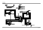
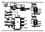
MONITOR OUT VIDEO

From SMPS Board

External Speaker

MONITOR OUT SOUND

+12V_AMP

1

2

BD701

TP06

TP07

TP05

TP04

5-3 ANALOG 3

TP04

TP05

TP06

TP07

This Document can not be used without Samsung’s authorization.

Содержание PPM42S3QX/XAA

Страница 1: ...DISPLAY TV Chassis D61B Model PPM42S3QX XAA PLASMA DISPLAY TV CONTENTS Specifications Alignment and Adjustments Exploded View and Parts List Electric Parts List Schematic Diagrams 1 2 3 4 5 SERVICE M...

Страница 2: ...79 D x 630 5 H mm 40 43 W x 3 11 D x 24 82 H inches 31 Kg 68 34 lbs without stand 107 Cm 42 Inches AC 120V 60Hz AC100 250V 50 60Hz 330 Watts 852 H X 480 V RS 232C IN Mini jack RS 232C OUT D SUB 9P VI...

Страница 3: ...and enters service mode If you fail to enter service mode repeat steps 1 and 2 above 2 1 2 Initial DISPLAY State of SERVICE MODE 2 1 2 A OSD DISPLAY 2 1 2 B Button Operations in SERVICE MODE 1 VSP943...

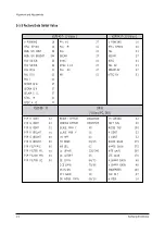
Страница 4: ...AV 01 SECAM AV 27 NTSC AV 01 ASI II 500 DNIe Video PC DVI PI P R CONT 32 PI P G CONT 32 PI P B CONT 32 PI P R BRIGHT 00 PI P G BRIGHT 00 PI P B BRIGHT 00 PI P FILTERIC 00 PI P FILTER ML 00 PI P FILTER...

Страница 5: ...LC 00 FI LTER YPASS 00 R GAMMA 32 G GAMMA 32 B GAMMA 32 H POSITION 00 V POSITION 00 H SIZE 00 V SIZE 00 OVERSCAN R 50 OVERSCAN G 50 OVERSCAN B 50 AD9888 Vi deo Comp PC CXA2101 Vi deo COMP R GAI N 71 1...

Страница 6: ...VSYNC WIDTH 02 HSYNC WIDTH 12 LOG PATTERN 00 LOG HIGH LEVEL 00 LOG LOW LEVEL 00 ASI COLORBAR 00 I C W B D ata V id e o S V H S C om p on e nt P C D V I D N Ie B r igh t 4 1 5 8 4 3 3 6 C o ntr ast 5...

Страница 7: ...At this time do not adjust the gain of AD9888 the Highlight W B does not need to be adjusted since its deviation falls within valid distribution range PC adjustment is same as DTV adjustment The offse...

Страница 8: ...t measure point High Light measure point V id e o S V H S C o m p o n en t P C D V I T im ing 9 2 5 LTH P A L B 7 2 0 p 6 4 0 4 8 0 6 0 H z 6 4 0 4 8 0 6 0 H z H L x 2 7 5 2 8 0 2 8 0 2 8 0 y 2 8 0 2...

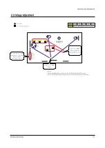
Страница 9: ...S Vs VSCAN VSET VA VE VSET VSCAN VE VA VS Adjust the S MPS voltage using the VR Variable Resistor Validate the SMPS voltage Not used by this Model Common use with Other Models S MPS Fan power source C...

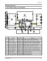
Страница 10: ...A BN96 00872A BN96 00873A BN96 01213A BN96 01214A BN96 01215A BN96 01217A BN94 00536A BN94 00536B Specification M3 S42D YD V3 42INCH SEMCO SMPS D65A V3 1 M3 S42SD YD D65A X MAIN BOARD LJ92 00758A V3 M...

Страница 11: ...HIPS V 1 T0001 BN96 00314C ASSY COVER P BACK PS42P3S AL5052 T1 2 DG 1 T0532 BN96 00676A ASSY MISC P FAN PPM42S3 2 M0764 BN96 00756A ASSY STAND P SCREW PPM50H3 SCREW PE BAG 1 T0073 BN96 00870A ASSY PD...

Страница 12: ...BOTTOM ASSY 42P3S AL5052 1 S N A T0915 BN61 00141A HOLDER MODULE 42P3 AL DIECASTING 4 S N A T0918 AA60 00110H SPACER FILTER 42P3 P U FROM 960 5 6 1 S N A T0918 AA60 00110J SPACER FILTER 50P3 P U Form...

Страница 13: ...nnector COMPONENT1 S Video Analog Digital Board CXA2151Q IC103 TP02 TP03 TP01 5 Schematic Diagrams Samsung Electronics Schematic Diagrams 5 1 5 1 ANALOG 1 TP01 TP02 TP03 This Document can not be used...

Страница 14: ...Schematic Diagrams 5 2 Samsung Electronics R246 To DC FAN FAN PART 50 R247 TILT SENSOR 3D COMB FILTER 5 2 ANALOG 2 This Document can not be used without Samsung s authorization...

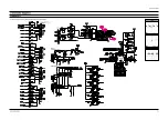
Страница 15: ...hematic Diagrams 5 3 MONITOR OUT VIDEO From SMPS Board External Speaker MONITOR OUT SOUND 12V_AMP 1 2 BD701 TP06 TP07 TP05 TP04 5 3 ANALOG 3 TP04 TP05 TP06 TP07 This Document can not be used without S...

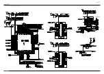
Страница 16: ...5 4 ANALOG 4 Schematic Diagrams 5 4 Samsung Electronics 74HCT573 74HCT573 This Document can not be used without Samsung s authorization...

Страница 17: ...Samsung Electronics Schematic Diagrams 5 5 5 5 CONTROL AA32 00013B This Document can not be used without Samsung s authorization...

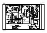
Страница 18: ...Schematic Diagrams 5 6 Samsung Electronics 5 6 SMPS 1 This Document can not be used without Samsung s authorization...

Страница 19: ...Samsung Electronics Schematic Diagrams 5 7 5 7 SMPS 2...

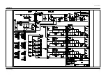
Страница 20: ...Schematic Diagrams 5 8 Samsung Electronics 5 8 SMPS 3...

Страница 21: ...Samsung Electronics Schematic Diagrams 5 9 5 9 SMPS 4...

Страница 22: ...Schematic Diagrams 5 10 Samsung Electronics 5 10 DIGITAL 1 Connector 50 63 HD Analog Digital board PC D SUB DVI SOUND 42 SD 42 HD TP08 TP10 TP09 TP08 TP09 TP10...

Страница 23: ...ng Electronics 5 11 TP11 TP12 TP13 TP14 TP16 TP19 TP17 TP18 TP15 Schematic Diagrams 5 11 DIGITAL 2 TP11 TP12 TP13 TP14 TP15 TP16 TP17 TP18 TP19 This Document can not be used without Samsung s authoriz...

Страница 24: ...Diagrams Samsung Electronics ANALOG EDID EPROM BNC Connector PC D SUB From SMPS board TP23 TP22 TP20 TP21 TP24 5 12 DIGITAL 3 TP20 TP21 TP22 TP23 TP24 This Document can not be used without Samsung s...

Страница 25: ...ics Schematic Diagrams 5 13 USER EPROM 256K RS232C IN Flash Memory B12 1204 002105 From Remote Control board RS232C OUT TP25 TP26 5 13 DIGITAL 4 TP26 TP25 This Document can not be used without Samsung...

Страница 26: ...5 14 Schematic Diagrams 5 15 TP27 TP28 5 14 DIGITAL 5 TP28 TP27 This Document can not be used without Samsung s authorization...

Страница 27: ...Schematic Diagrams 5 15 5 15 LVDS Connector 5 15 DIGITAL 6 This Document can not be used without Samsung s authorization...

Страница 28: ...5 16 Schematic Diagrams Samsung Electronics 5 16 DIGITAL 7 This Document can not be used without Samsung s authorization...

Страница 29: ...Samsung Electronics Schematic Diagrams 5 17 DIGITAL EDID EPROM DVI Connector 5 17 DIGITAL 8 This Document can not be used without Samsung s authorization...

Отзывы: