background image

38

ENG

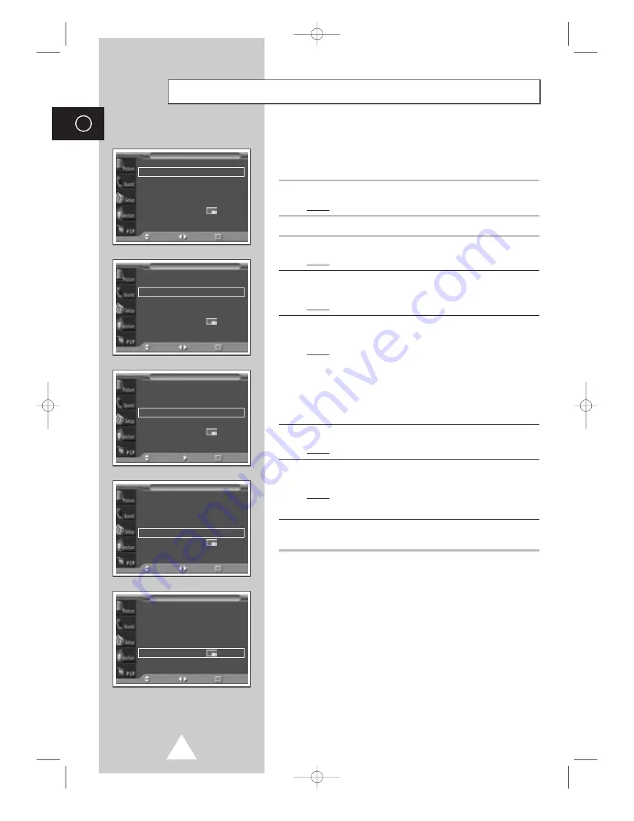
You can display a sub picture within the main picture. In this way
you can monitor the video input from any connected devices while
monitoring other video input.

1

Press the MENU button.

Result:

The main menu is displayed.

2

Press the 

or 

button to select 

PIP

.

3

Press the 

button.

Result:

The 

PIP

option is selected.

4

Set to 

On 

by pressing the 

œ

or 

button for activating the PIP

feature.

Result:

The options available in the 

PIP

group are displayed.

5

Press the 

or 

button to select 

Sel.

. Select a source of the sub

picture by pressing the 

œ

or 

button.

Result:

The sources are displayed in the following order:

Video - S-Video - Component1 - Component2 -
PC1 - PC2 - DVI

For further details about selecting a source, refer to
“Selecting the source of sub picture depending on the source
of main picture” on page 39.

6

Press the 

or 

button to select 

Swap

. Press the 

button.

Result:

The main picture and sub picture are interchanged.

7

Press the 

or 

button to select 

Size

. Select a size of the sub

picture by pressing the 

œ

or 

button.

Result:

The sizes are displayed in the following order:

Large - Small - Double1 - Double2

8

Press the 

or 

button to select 

Locate

. Select a location of the

sub picture by pressing the 

œ

or 

button.

Viewing the Picture In Picture (PIP)

PIP

œ

œ

On  

Sel.

œ

œ

Video  

Swap

Size

œ

œ

Large  

Locate

œ

œ  

Sound Sel.

œ

œ

Main  

PIP

Move

Sel.

Return

PIP

œ

œ

On  

Sel.

œ

œ

Video  

Swap

Size

œ

œ

Large  

Locate

œ

œ  

Sound Sel.

œ

œ

Main  

PIP

Move

Sel.

Return

PIP

œ

œ

On  

Sel.

œ

œ

Video  

Swap

Size

œ

œ

Large  

Locate

œ

œ  

Sound Sel.

œ

œ

Main  

PIP

Move

Sel.

Return

PIP

œ

œ

On  

Sel.

œ

œ

Video  

Swap

Size

œ

œ

Large  

Locate

œ

œ  

Sound Sel.

œ

œ

Main  

PIP

Move

Sel.

Return

PIP

œ

œ

On  

Sel.

œ

œ

Video  

Swap

Size

œ

œ

Large  

Locate

œ

œ  

Sound Sel.

œ

œ

Main  

PIP

Move

Enter

Return

BN68-00457B-01_ENG  2003.10.23  3:21 PM  Page 38

Содержание PPM42S3

Страница 1: ...uctions Before operating the unit please read this manual thoroughly and retain it for future reference ON SCREEN MENUS PICTURE IN PICTURE PIP VIDEO WALL MDC MULTIPLE DISPLAY CONTROL Intended for Commercial Use and Operation BN68 00457B 01_ENG 2003 10 23 3 20 PM Page 1 ...

Страница 2: ...horized changes or modifications to this equipment may void the user s authority to operate it Caution To prevent electric shock match the wide blade of plug to the wide slot and fully insert the plug Attention pour eviter les chocs electriques introduire la lame le plus large de la fiche dans la borne correspondante de la prise et pousser jusqu au fond Important One Federal Court has held that un...

Страница 3: ...ed with slots in the cabinet for ventilation to protect it from overheating Do not block these openings with any object and do not place the PDP on a bed sofa rug or other similar surface Do not place it near a radiator or heat register If you place the PDP on a rack or bookcase ensure that there is adequate ventilation and that you ve followed the manufacturer s instructions for mounting Operate ...

Страница 4: ...o qualified service personnel Unplug the unit from the wall outlet and refer servicing to qualified service personnel under the following conditions when the power supply cord or plug is damaged if liquid has been spilled on the unit or if objects have fallen into the unit if the PDP has been exposed to rain or water if the PDP does not operate normally by following the operating instructions if t...

Страница 5: ...t consult an elec trician for replacement of the obsolete outlet Protect the power cord from being walked on or pinched particularly at plugs convenience receptacles and the point where they exit from the apparatus Only use attachments accessories specified by the manufacturer Use only with cart stand tripod bracket or table specified by the manufacturer or sold with the apparatus When a used caut...

Страница 6: ...n Drive Suite 290 Irvine CA92612 USA Warning User must use shielded signal interface cables to maintain FCC compliance for the product Provided with this monitor is a detachable power supply cord with IEC320 style terminations It may be suitable for connection to any UL Listed personal computer with similar configuration Before making the connection make sure the voltage rating of the computer con...

Страница 7: ... text such as stock market reports video game displays station logos web sites or computer graphics and patterns should be limited as described above for all PDP displays Displaying stationary images that exceed the above guidelines can cause uneven aging of PDP Displays that leave subtle but permanent burned in ghost images in the PDP picture To avoid this vary the programming and images and prim...

Страница 8: ...emain lit Height The PDP can normally operate only under 2000m in height It might abnormally function at a place over 2000m in height and do not install and operate there Warranty Warranty does not cover any damage caused by image retention Burn in is not covered by the warranty EUROPEAN NOTICE Products with the CE marking comply with the EMC Directive 89 336 EEC 92 31 EEC 93 68 EEC and the Low Vo...

Страница 9: ... plug Replacement covers are available from your dealer If the fitted plug is not suitable for the power points in your house or the cable is not long enough to reach a power point you should obtain a suitable safety approved extension lead or consult your dealer for assistance However if there is no alternative to cut off the plug remove the fuse and then safely dispose of the plug Do NOT connect...

Страница 10: ...ng the Display Vertically 18 Before Using the Video Wall and the Multiple Display Contol function 18 Connecting Speakers 19 Switching On and Off 21 Choosing Your Language 21 USING YOUR DISPLAY Selecting the Color System Video or S Video Mode 22 Changing the Picture Mode 22 Adjusting the Picture Settings 23 Adjusting the Picture Settings PC or DVI Mode 24 Selecting the Picture Size 25 Activating De...

Страница 11: ... Listening to the Sound of the Sub Picture 40 ADDITIONAL INFORMATION AND CONNECTIONS Viewing Pictures From External Sources 40 Connecting to the Audio Video Input 41 Connecting to the S Video Input 42 Connecting to the DVD DTV RECEIVER Input 42 Connecting to the DVI Input 43 Connecting to the RGB PC Input 43 Setting up Your PC Software Windows only 44 Pin Configurations 45 Input Mode PC DVI 46 Pow...

Страница 12: ...operated with source key MENU Menu display and exit VOL Volume adjustment Adjust an option value respectively VOL Enter to the selected menu SEL Control the cursor in the menu I Press to turn the PDP on and off Speaker Speaker a b c PPM42S3 PPM50H3 PPM63H3 a b c a Power Indicator Power Off Red Power On Off Timer On Green b Remote Control Signal Receiver Aim the remote control towards this spot on ...

Страница 13: ... PC e COMPONENT2 RGB2 PC2 IN Connect for input of an Analog RGB or Y Pb Pr video signal from in PC DVD or HD devices PC Mode from this page onward means PC1 PC2 mode using RGB1 PC1 and RGB2 PC2 f VIDEO IN Video and audio inputs for external devices such as VCR DVD video game device or video disc players or for external devices with an S Video output S VIDEO g COMPONENT1 IN Video Y Pb Pr and audio ...

Страница 14: ... FOR THIS MONITOR CHANGE CONFIRMATION INFORMATION DISPLAY PIP FUNCTIONS PIP ON OFF SIZE SELECTION SIZE LOCATION SELECTION LOCATE INPUT SOURCE SELECTION SOURCE INTERCHANGE THE MAIN AND THE SUB PICTURE SWAP SOUND SELECTION S SEL PICTURE SIZE SELECTION PICTURE STILL SETTING THE TIMER AUTO ADJUSTMENT IN PC MODE PDP OFF ZOOM PANNING MENU DISPLAY ONLY PC MODE MULTIPLE DISPLAY CONTROL VOLUME DECREASE NEX...

Страница 15: ...ol on the battery against on the remote control 3 Replace the cover by aligning it with the base of the remote control and pressing it back into place Inserting the Batteries in the Remote Control Assembling the Stand Base Fit the Stand Base into the guide hole on the bottom of the monitor and tighten the left and right sides using four screws for each side Two or more people should carry the PDP ...

Страница 16: ...after assembling the bracket This wall mount bracket installation guide is for the following models WMN4230 WMN5030 WMN6330 This installation guide may be different from the PDP User s manual Please refer to the proper installation guide for your product Installation Notes Do not install the PDP on any place other than vertical walls To protect the performance of the PDP and prevent troubles avoid...

Страница 17: ...lease tightly secure the wall mount bracket to the wall to avoid injury from a falling PDP 3 Tighten the screws of the plastic hanger to the back side of the PDP 4 Put the 4 pegs on the PDP in the grooves of the wall mount bracket and pull down on the PDP to secure it to the wall mount bracket Tighten the screws as shown so that the PDP cannot be separated from wall mount bracket The exterior of t...

Страница 18: ...2 Video Wall function 1 Please create ID for each PDP before installing them close together It may be difficult to create IDs when operating the remote control for PDPs that are installed close to each other 2 Press the MDC button on the remote control Select ID input on the menu Use the numeric buttons to enter the ID for PDP adjustment You can operate the remote control only for the PDP that has...

Страница 19: ...ker bracket using the screws removed from the PDP When moving your PDP do NOT hold the speaker connected to your PDP It may damage the bracket clamping the speaker and your PDP together and result in a drop of your PDP and a risk of personal damage and injury PPM42S3 PPM50H3 PPM63H3 PPM42S3 PPM50H3 PPM63H3 PPM42S3 PPM50H3 PPM63H3 BN68 00457B 01_ENG 2003 10 23 3 21 PM Page 19 ...

Страница 20: ...io cable to the external speaker output jack on the rear of the PDP matching the and ends of the cable with the diagram on the PDP PPM42S3 PPM50H3 PPM63H3 The speakers MUST have to a power handling capability of 10 watts minimum impedance 8Ω When you connect the speaker wire to the external speaker out connector first bind the speaker wire round the ferrite core to secure it BN68 00457B 01_ENG 200...

Страница 21: ...ains lead is attached to the rear of your PDP If you have purchased this PDP in the United Kingdom refer to page 9 for further instructions on plug wiring 1 Plug the mains lead into an appropriate socket Result The Standby indicator on the front of the PDP lights up The main voltage is indicated on the rear of the PDP and the frequency is 50 or 60Hz 2 Press the I button on the front of the PDP or ...

Страница 22: ... Picture Move Sel Return You can select the type of picture which best corresponds to your viewing requirements 1 Press the MENU button Result The options available in the Picture group are displayed 2 Press the button 3 Press the or button to select Mode Select the option by pressing the œ or button Result The following modes are available depending on the input source Dynamic Standard Movie Cust...

Страница 23: ...tings press the button to store them 6 Press the MENU button Result The options available in the Picture group are displayed again 7 Press the or button to select Color Tone Select the option by pressing the œ or button The color tones are displayed in the following order Normal Warm1 Warm2 Cool2 Cool1 If you make any changes to these settings the picture mode is automatically switched to the Cust...

Страница 24: ... or button to select color Adjust Press the button Result The Color Adjust menu is displayed When select the Color Tone to Custom the Color Adjust menu is displayed The Color Adjust menu can not be selected in DVI mode 9 Press the or button to select the option Red Green Blue to be adjusted Press the œ or button Result The horizontal bar is displayed Move the horizontal bar s cursor left or right ...

Страница 25: ... by pressing the or button Wide Normal PC or DVI Mode You can also set these options simply by pressing the P SIZE button Activating Deactivating the Digital Noise Reduction Feature If the signal received by your PDP is weak you can activate this feature to reduce any static and ghosting that may appear on the screen 1 Press the MENU button Result The options available in the Picture group are dis...

Страница 26: ...nu is displayed 2 Press the or button to select Sound Result The options available in the Sound group are displayed 3 Press the button Result The Mode is selected 4 Select the option by pressing the œ or button The sound effects are displayed in the following order Custom Standard Music Movie Speech You can also set these options simply by pressing the S MODE Sound Mode button Changing the Sound M...

Страница 27: ...ect the option volume balance equalizer to be adjusted by pressing the œ or button Press the or button to reach the required setting 6 When you are satisfied with the settings press the button to store them If you make any changes to the equalizer settings the sound mode is automatically switched to the Custom Adjusting the Sound Settings Equalizer Custom œ œ Move Adjust Store 100 300 1K 3K 10K R ...

Страница 28: ...eech 1 Press the MENU button Result The main menu is displayed 2 Press the or button to select Sound Result The options available in the Sound group are displayed 3 Select the required option Auto Volume Melody Pseudo Stereo Virtual Surround by pressing the or button 4 Press the œ or button to change the setting Off or On Extra Sound Settings Mode œ œ Custom Equalizer Auto Volume œ œ Off Melody œ ...

Страница 29: ...enu is displayed again 8 Press the or button to select Scale Press the button Adjust the screen scale by pressing the œ or button 9 When you are satisfied with the setting press the button to store Press the or button to select Reset Press the button The position and scale settings are replaced with the factory default values Adjusting the Screen Position and Scale ENG Screen Adjust Key Lock œ œ O...

Страница 30: ...s the button to store 10 Press the MENU button Result The Image Lock menu is displayed again 11 Press the or button to select Zoom Panning Press the button Result The Zoom Panning menu is displayed with the Zoom selected You can also do simpley by pressing the ZOOM button 12 Press the œ or button to reach the required magnification 13 Press the or button to select Panning Move the magnified pictur...

Страница 31: ...tup selected 6 Select the ID setup number by pressing the œ or button 7 Press the or button to select ID Input Enter ID input number by using the numeric buttons To operate the multi control function PDP1 and PDP2 should be set in the ID Setup mode When entering the ID Input number of PDP1 while the PDP is set in the ID Input mode only PDP1 is switched to the Menu screen and you can operate the re...

Страница 32: ...with the settings press the MENU button Result The Burning Protection menu is displayed again 10 Press the or button to select Signal Pattern Set to On by pressing the œ or button for removing the residual image 11 Press the or button to select All White Set to On by pressing the œ or button for removing the residual image after making the screen white The Signal Pattern and All White feature are ...

Страница 33: ...n Divider Press the button 8 Select the option 2x2 3x3 4x4 1x5 5x1 by pressing the or button Press the button 9 Press the œ or button to select the position of the screens PIP function does not operate during Video Wall operation Setting the Multiple Screen ENG Video Wall Set œ œ On Screen Divider Move œ œ Sel Return Video Wall Set œ œ On Screen Divider Move Enter Return Screen Adjust Key Lock œ œ...

Страница 34: ...equency and horizontal frequency are displayed Displaying the PC Information PC Information Resolution 1024x768 V Frequency 60 H Frequency 48 Return Image Lock Key Lock œ œ Off Multi Control Burning Protection Video Wall Information Setup Move Enter Return You can view the setting status you select by pressing the INFO button on the remote control Displaying the Setting Information Mode Video Pict...

Страница 35: ...nute by pressing the or button Set the clock first If you have not yet set the clock you can not set other options of the Time menu 6 Press the or button to select Clock Display Set to On by pressing the œ or button for displaying the current time You can also do simply by pressing the CLOCK DISPLAY button 7 When you are satisfied with the settings press the button to store them Setting and Displa...

Страница 36: ...e œ or button for tuning to the volume of your choice at the time switching on 7 Press the or button to select On Time Press the œ or button to move to the hour or minute Set the time at which you wish the PDP to be switched on automatically by pressing the or button 8 Press the or button to select Off Time In the same above set the time at which you wish the PDP to be switched off automatically 9...

Страница 37: ... Language English Time Selectable Fan œ œ Off Film Mode œ œ Off Function Move Sel Return When a video input source is from a film such as movies this feature identifies the source and changes to the corresponding screen 1 Press the MENU button Result The main menu is displayed 2 Press the or button to select Function Result The options available in the Function group are displayed 3 Press the butt...

Страница 38: ...picture on page 39 6 Press the or button to select Swap Press the button Result The main picture and sub picture are interchanged 7 Press the or button to select Size Select a size of the sub picture by pressing the œ or button Result The sizes are displayed in the following order Large Small Double1 Double2 8 Press the or button to select Locate Select a location of the sub picture by pressing th...

Страница 39: ...E Used to assign a source of sub picture SWAP Used to interchange the main picture and the sub picture S SEL Used to listen the sound of the sub picture Viewing the Picture In Picture PIP continued ENG Video S Video Component1 Component2 PC1 PC2 DVI Video S Video Component1 Main picture Sub picture DVI PC2 PC1 Component1 Selecting the source of sub picture depending on the source of main picture B...

Страница 40: ... to the Sound of the Sub Picture Once you have connected up your various audio and video systems you can view different sources by selecting the appropriate input 1 Check that all the necessary connections have been made 2 Switch your PDP on then press the SOURCE button Result The input sources available are displayed 3 Press the or button to select the required input source 4 Press the button to ...

Страница 41: ...you have a second VCR and wish to copy cassettes tape connect the source VCR to VIDEO IN and the target VCR to VIDEO OUT so that you can redirect the signal from VIDEO IN to VIDEO OUT When you wish to record a programme connect the receiver to VIDEO IN and the VCR to VIDEO OUT so that you can redirect the signal from VIDEO IN to VIDEO OUT Whenever you connect an audio or video system to your PDP e...

Страница 42: ...er VCR To play picture and sound both the S VIDEO and RCA connectors must be used and Connecting to the DVD DTV RECEIVER Input The COMPONENT1 IN or R Pr G Y B Pb video and AUDIO connectors are used for equipment with a DVD DTV RECEIVER output 480i 480p 720 1080i Pr Y Pb and Rear of the PDP or Y Pb Pr L R or Digital Set Top Box DVD BN68 00457B 01_ENG 2003 10 23 3 21 PM Page 42 ...

Страница 43: ...eo and AUDIO connectors are used for equipment with a DVI output Personal Computer and Rear of the PDP The RGB1 PC1 IN or R Pr G Y B Pb H V and AUDIO connectors are used for interfacing with your PC Personal Computer Rear of the PDP or BN68 00457B 01_ENG 2003 10 23 3 21 PM Page 43 ...

Страница 44: ...ings Control Panel When the control panel screen appears click on Display and a display dialog box will appear Select the Settings tab in the display dialog box The two key variables that apply the PDP PC interface are Resolution and Colours The correct settings for these two variables are Size sometimes called Resolution 640 x 480 pixels PPM42S3 1024 x 768 pixels PPM50 63H3 Colour 24 bit colour m...

Страница 45: ... M D S Data5 22 T M D S Clock Shield 23 T M D S Clock 24 T M D S Clock DVI Input Connector 24Pin Pin RGB PC IN 1 Red R 2 Green G 3 Blue B 4 Grounding 5 Grounding DDC 6 Red R Grounding 7 Green G Grounding 8 Blue B Grounding 9 Reserved 10 Sync Grounding 11 Grounding 12 Data DDC 13 Horizontal sync 14 Vertical sync 15 Clock DDC RGB PC Input Connector 15Pin Pin Signal 1 Carrier Detect 2 Receive Data 3 ...

Страница 46: ...td A mark means that this mode can be supported A mark means that this mode is recommended VGA SVGA XGA WVGA SXGA WXGA UXGA 70 85 85 70 85 60 72 75 85 56 60 72 75 85 60 70 75 85 60 72 75 85 60 75 60 75 60 75 60 60 60 31 5 37 9 37 9 31 5 37 9 31 5 37 9 37 5 43 3 35 2 37 9 48 1 46 9 53 7 48 4 56 5 60 0 68 7 29 8 35 1 36 0 37 0 31 8 67 5 64 0 80 0 47 7 60 1 47 8 48 2 75 0 Resolution 640 x 350 640 x 4...

Страница 47: ...ontal Sync Vertical Sync Video Power Indicator Normal Operation Active Active Active Off Standby Mode Inactive Active Blanked Red Blinking 1 sec Interval Suspend Mode Position A1 Active Inactive Blanked Red Blinking 1 sec Interval Power off Mode Position A2 Inactive Inactive Blanked Red Blinking 1 sec Interval Power saving Function Mode This monitor automatically returns to normal operation when h...

Страница 48: ...m selected is correct Plug your PDP into a different mains socket Replace the remote control batteries Clean the upper edge of the remote control transmission window Check the battery terminals Care and Maintenance Identifying Problems Do not put the PDP near extremely hot cold humid or dusty places Do not put the PDP near appliances that create magnetic fields Keep the ventilation openings clear ...

Страница 49: ...PPM42S3 42 inch PPM50H3 50 inch PPM63H3 63 inch Native pixel resolution PPM42S3 852 x 480 H x V PPM50H3 PPM63H3 1366 x 768 Color systems PAL SECAM NTSC NT3 58 NT4 43 Sound Stereo Virtual Dolby Audio output power 10W 10W 8Ω Power supply U S A Canada AC120V 60Hz Other countries AC100 250V 50 60Hz Power consumption PPM42S3 380 Watts PPM50H3 480 Watts PPM63H3 630 Watts Video inputs VIDEO IN VIDEO S VI...

Страница 50: ...50 Memo ENG BN68 00457B 01_ENG 2003 10 23 3 21 PM Page 50 ...

Страница 51: ...51 Memo ENG BN68 00457B 01_ENG 2003 10 23 3 21 PM Page 51 ...

Страница 52: ...B 01 AFTER SALES SERVICE Do not hesitate to contact your retailer or service agent if a change in the performance of your product indicates that a faulty condition may be present BN68 00457B 01_ENG 2003 10 23 3 21 PM Page 52 ...

Отзывы: